Power Conversion Systemlink
Last updated: November 13, 2024
Overviewlink
The power conversion system (PCS) has three main functions:
- Pre-charging the HV bus on the vehicle prior to closing HV pack contactors
- Converting the pack DC high voltage down to low voltage to power the low voltage (low voltage) system of the vehicle and support the low voltage battery
- Converting AC to DC and stepping it up to charge the HV battery from AC wall power
AC and DC side terminals of the PCS are galvanically isolated.
The maximum AC charge current per line depends on the vehicle configuration. See Vehicle Configurations and Their Maximum Charge Current for more information.
Note
For more information on HV battery packs, see
On the low voltage side, the PCS can convert up to 2.5kW of power between the DC link and low voltage output. The illustration below displays the location of the PCS within the front Ancillary Bay.
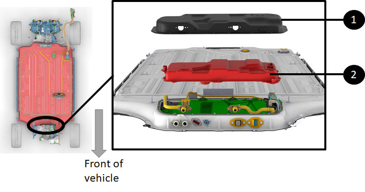
Location of Power Conversion System (PCS)link
The PCS is located in the front Ancillary Bay of the HV battery.
 |
|---|
| 1. Front Ancillary Bay access cover 2. PCS directly underneath |
| Location of the PCS in front HV Ancillary Bay |
Accessing the PCSlink
The PCS sits on a tray on top of the high voltage controller (HVC). The PCS is accessed once the front Ancillary Bay cover is removed.
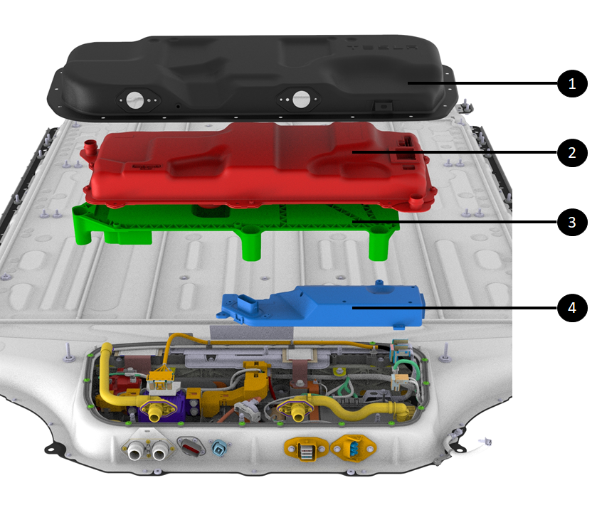 |
|---|
| 1. Front Ancillary Bay access cover 2. PCS 3. PCS tray 4. HVC right under the PCS tray |
| Accessing the PCS |
DC Connection to the PCSlink
Although the Power Conversion System (PCS) is not used when fast charging, it still needs to be connected to the DC link of the HV battery for two functions:
- Pre-charging the DC link but to pack voltage prior to closing contactors (See
Non-Structural High Voltage Battery Pack Theory of Operation for more details). - Converting High Voltage (HV) from the HV battery to low voltage to support the vehicle low voltage battery and the vehicle low voltage system.
The PCS DC side is connected as follows to the pack DC link:
- The HV positive of the PCS is connected to the positive DC link busbar coming from the positive pack contactor.
- There is a 63A fuse in between the PCS HV connection and the busbar.
- The PCS HV negative connection is from a cable bolted on the main DC link negative busbar (via a round terminal) that connects to the negative pack contactor.
- The negative link from the DC link to the PCS is not fused in contrary to the positive one.
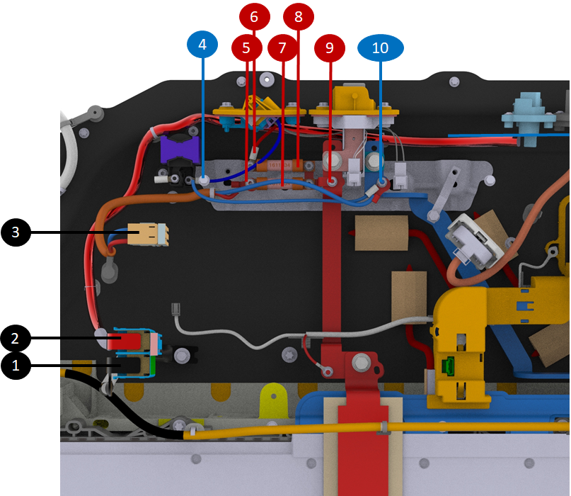 |
|---|
| 1. DCDC 12V negative (directly bolted down to enclosure) 2. DCDC 12V positive (route to single pole connector at front of HV battery) 3. HV connector to PCS (connect DC link to PCS) 4. DC negative cable to/from AC compressor connector 5. DC link positive to PCS 6. DC positive to AC compressor connector 7. 63A fuse on PCS DC link positive 8. 63A fuse on AC compressor DC link positive 9. DC link positive tap for AC compressor, PCS, and Electromagnetic Interference (EMI) filter 10. DC link negative tap for AC compressor, PCS and EMI filter |
| Connection of PCS to DC Link HV |
AC Connection to the PCSlink
The PCS converts AC input from wall power through the charge port to DC voltage when charging the HV battery. The PCS has a dedicated connection to the HV battery inlet charge port busbar connector for this.
The Palladium pack is designed to accommodate both single-phase and three-phase without any hardware differences. This is done by having a 6-pole AC connector, where 4 pins are used for three-phase charging in EMEA and APAC markets. The 2 other pins are used for single-phase charging in North American market.
Where four pins are used to connect the PCS to AC input with an AC connection, the two other pins connect to the Fast Charge link.
Note
The single-phase HV battery needs a dummy jumper plug on the 6 pin connector to connect the DC busbar to the PCS harness. Inside this jumper plug, the two pins from the fast charge links are connected to the four pins of the PCS AC input, this way forwarding single phase power from the charge port through the fast charge link and the jumper plug to the PCS.
- Three-phase markets: AC charging through AC harness and 6P connector with 4 pins populated (L1, L2, L3, N) directly into the PCS harness.
- Single-phase markets: AC charging through DC busbar with 6P "jumper plug" to jump connection AC header pins from DC busbar to PCS harness.
Note
On the three-phase HV battery, instead of using a dummy plug, the three-phase AC charging harness from the charge port connects directly to 4 PCS pins of the 6p connector, leaving the 2 fast charge link pins disconnected.
Note
The dedicated AC charge connector was not populated directly at start of production (SOP). At SOP and only for North American market, the DC charge inlet had connections directly to the PCS AC inlet.
The first diagram below shows the AC connections are at the rear of the battery. The second diagram shows an overview at the HV battery level and shows how AC signals travel from rear to front of HV battery to reach the PCS.
 |
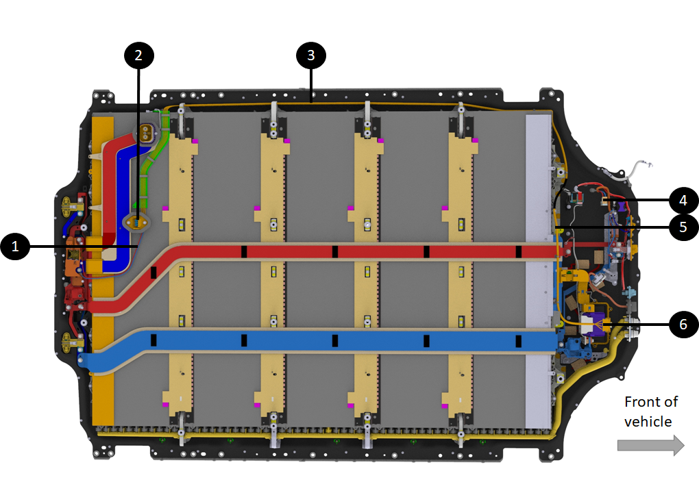
|---|
| 1. Harness bundle taking AC signals from the rear of the HV battery to PCS at the front Ancillary Bay 2. Same harness spread under the HV battery enclosure 3. HV battery inlet charge port busbar connector 4. Single busbar to charge port (negative when DC charging, single-phase when AC charging in North America) 5. Single busbar to charge port (positive when DC charging, single-phase when AC charging in North America) 6 & 7. Charge port to DC link connections for single-phase AC charging in North America (different routing at SOP - straight from DC charge port inlet to PCS) 8. (Not present at SOP)
|
| Charge Port Header, 6-Pole Connector, and Connections to PCS AC Input (Detailed view) |
 |
|---|
| 1. Charge port to DC link connections for single-phase AC charging in North America (different routing at SOP - straight from DC charge port inlet to PCS) 2. (Not present at SOP)
3. Harness bundle taking AC signals from rear of HV battery to PCS at front Ancillary Bay 4. HV connector to PCS (connect DC link to PCS) 5. Harness bundle taking AC signals from rear of HV battery to PCS at front Ancillary Bay 6. PCS AC input connector |
| Charge Port Header, 6-Pole Connector, and Connections to PCS AC Input (Overview) |