First Rowlink
Last updated: January 06, 2025
Overviewlink
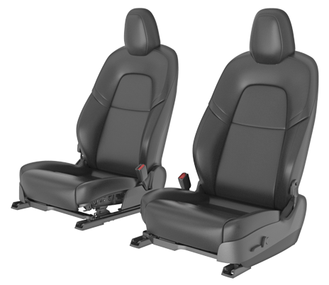
The Model Y has two options for first row seating. The first option is a standard five person seating capacity with a driver and passenger seat in the front row and a three passenger bench seat with powered fold-flat backrests in the rear. The rear seats are also capable of reclining. The second option is for seven person seating capacity with a driver and passenger seat in the front row, a three passenger bench seat (with the capability to slide and pivot forward), and two person seating capacity third row.
 |
|---|
| First Row Seats |
 |
|---|
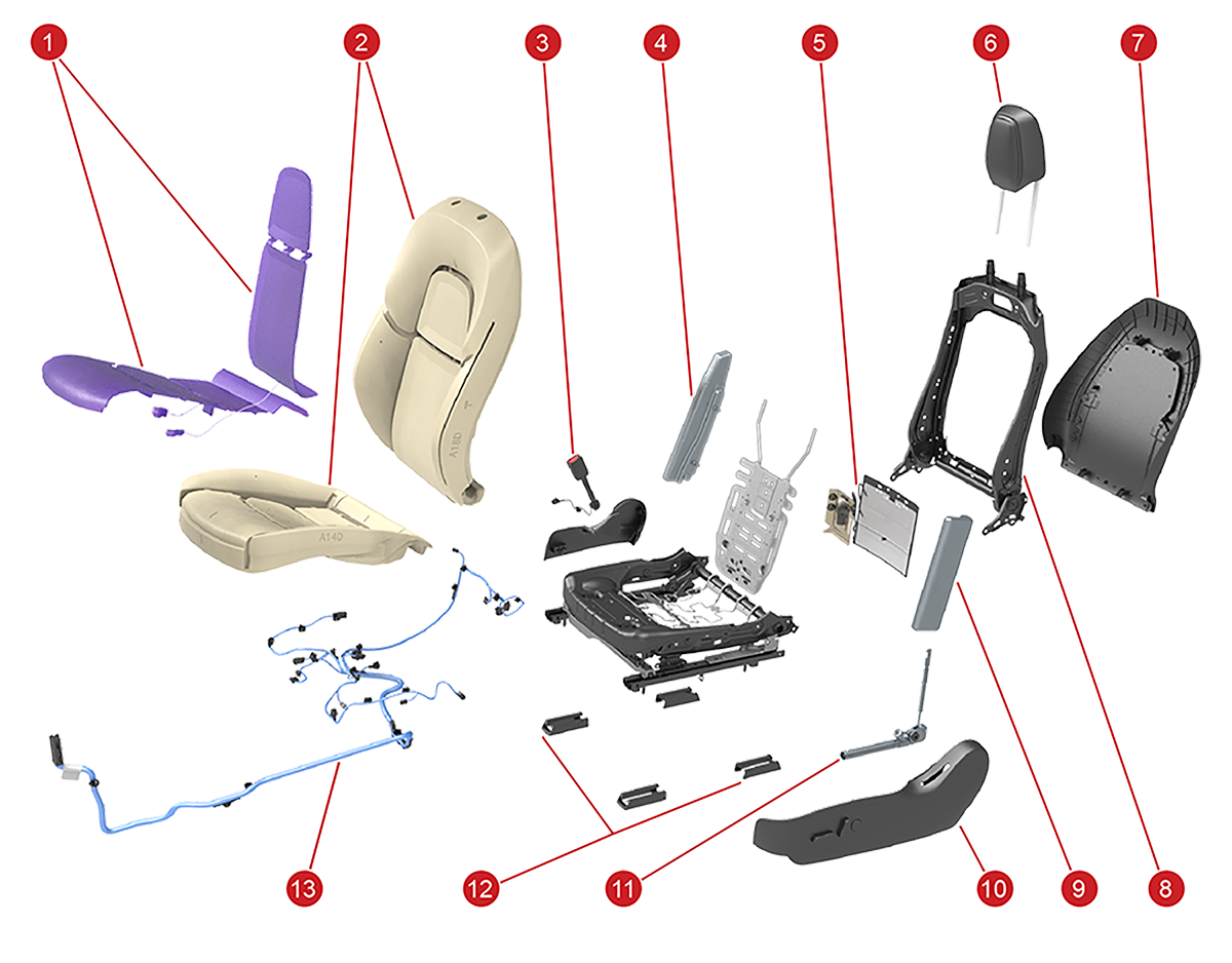
| 1. Heater pad 2. Seat foam 3. Seat belt buckle 4. Side air bag 5. Pneumatic lumbar support 6. Headrest 7. Seat back trim cover 8. Frame seat back 9. Side air bag 10. Side shield trim 11. Seat belt pretensioner 12. Seat track cover (x4 total) 13. Wire harness |
Serviceabilitylink
Model Y passenger seat at SOP is non-serviceable as the seat is equipped with an Occupant Classification System (OCS) that cannot be calibrated in the field (See for more information on the OCS). It is possible to calibrate the Model Y front seat motors. This seat calibration routines runs each of the individual motors into their endstops, this calibrates the seat into knowing where the seat is throughout the duration of travel.
Model Y driver seat is serviceable as it does not have an OCS but has a Seat Belt Reminder for an occupancy switch. Like passenger seat, the driver front seat can also be calibrated for all of the motors.
The first step in diagnosis should be to run the self test routines provided in Toolbox. These routines check for communication to every motor as well as the seat heater. If one of these tests fail it can point towards soft set connectors or failed component.
Coverslink
Component Descriptionlink
Model Y seats are available in both white and black Polyurethane (PUR). This material is a leather alternative.
Theory of Operationlink
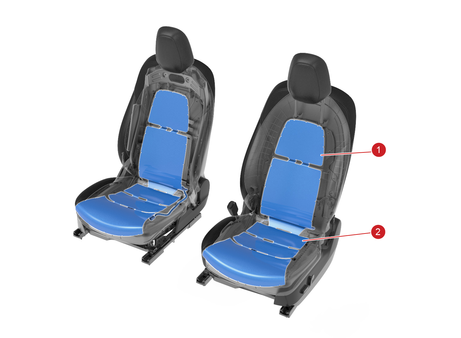
Model Y first row seat covers are secured to the foam with hook-and-loop fastening strips, which helps create the different panels on both the seat cushion and seat back. Then, sandwiching the foam, the cover is attached to the frame with various clips that are pulled taught on the frame to maintain the seat shape. There is also stitch detailing within the seat to help form the shape around the foam.
 |
|---|
| The seat cover attaches to the frame on the outer edges and attaches to the foam on the middle panel trenches |
| First Row Seat Cushion Cover |
 |
|---|
| The seat cover attaches to the frame on the outer edges and attaches to the foam on the middle panel trench |
| First Row Seat Back Cover |
Serviceabilitylink
Cleaninglink
Cleaning PUR seats with some conventional cleaners (especially alcohol-based) can cause performance and appearance degradation. Do NOT use products containing bleach (sodium hypochlorite). It is therefore important to clean seats with only approved cleaners. Below is a list of approved cleaners:
- Clorox NON Bleach Disinfecting Wipes
- Formula 409
- Seventh Generation NON Bleach Disinfecting Wipes
For White PUR ONLY, isopropyl alcohol is the strongest solvent that can be used without damaging the seat material. Moisten a soft cloth with warm water and isopropyl alcohol and gently wipe the stain in a circular motion.
Warning
Isopropyl alcohol should not be used on Black PUR.
Foam/Padlink
Component Descriptionlink
The seat foam, also referred to as the seat pad, provides comfort and stability to occupants.
Serviceabilitylink
If the seat foam and covers have not been installed appropriately it can feel or look as if the seat is missing foam or that the foam has collapsed. Because the foam is sandwiched between the cover and upholstery support, it is possible that it could have been misaligned during install. In some rare cases, the way in which a customer ingresses or egresses from the vehicle can apply pressure on the outmost edge of the cover and foam, causing the foam to get caught on the frame and not maintain it's full shape. This can be resolved by refitting the cover and foam.
Seat Heatlink
Component Descriptionlink
Model Y first row has heating elements in both the seat cushion and seat back of the driver and passenger seats.
 |
|---|
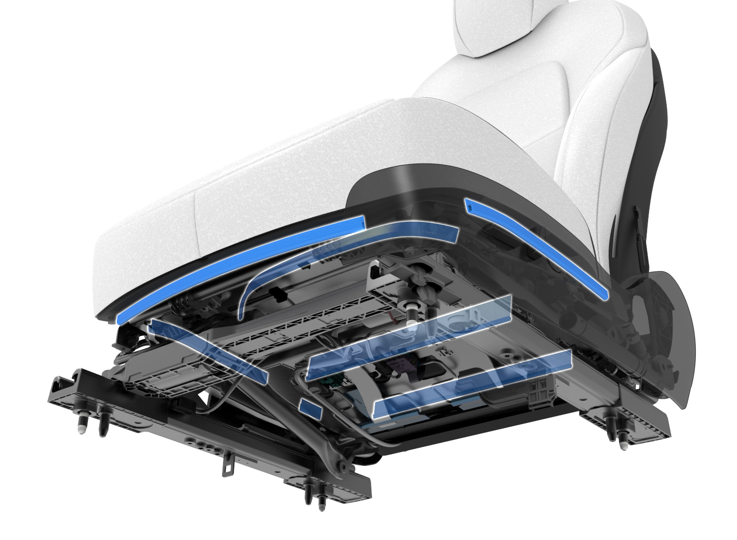
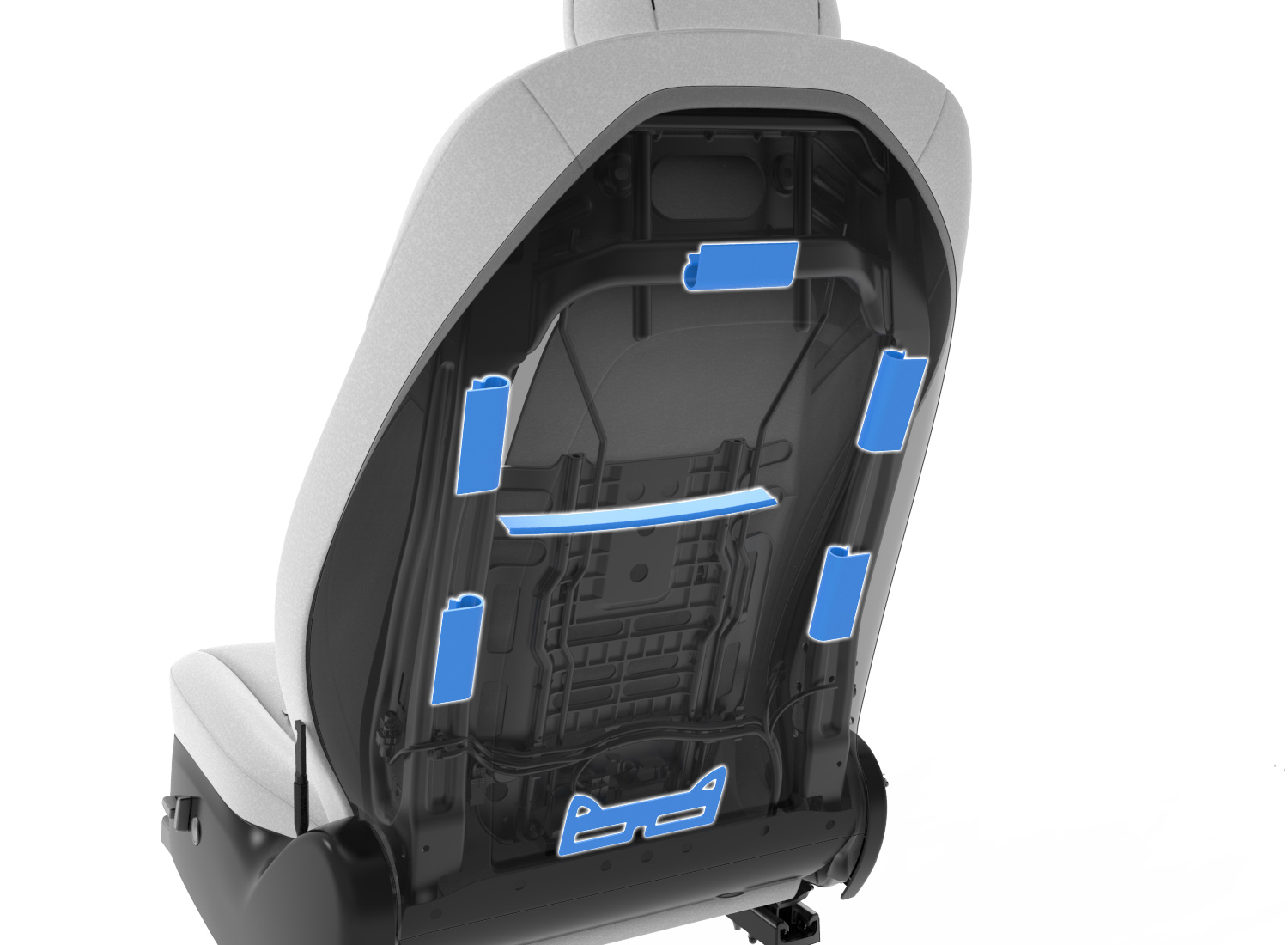
| 1. Backrest seat heater mat 2. Seat cushion heater mat |
| First Row Seat Heat |
The seat heater is made up of the following components:
- High side driver
- Pulse Width Modulation (PWM)
- Negative Temperature Coefficient (NTC) thermistors
- Resistive pad
The heating element, or resistive pad, is located only in the center panels of the seat back and seat cushion, the heating element is not located in the side bolsters.
Auto Seat Heatlink
Auto Seat Heat is a feature where the first row seat heaters will turn on as the vehicle reaches the desired set temperature. Auto Seat Heat only runs if Auto HVAC and Auto Seat Heat mode are enabled. These features are chosen via the UI. Auto Seat Heat is only for the first row seats and does not enable the rear seat heaters. The intensity of the seat heat is based off of several temperatures that from vehicle sensors as well as estimated values. Auto Seat Heat will run if the following temperature conditions are true:
- Ambient Temperature is below 20C
- Cabin Interior Temperature (estimated value) is below 25C
- Cabin Temperature Interior Sunny is below 35C
Helpful signals for this to monitor these temperatures: VCFRONT_tempAmbientFiltered VCRIGHT_cabinTempInterior
The intent of these various temperature parameters is to not run the seat heater when the vehicle is already warm. The intensity of the seat heater duty cycle is a function of the cabin environment, it will start off at the maximum duty cycle and slowly come down. The relative intensity is based off the chosen set temperature of the user. The golden set temperature that this feature is modeled after is 22C within the cabin.
If there are any issues with the THS Sensor, cabin temperature probe sensor or the ambient temperature sensor, the vehicle cannot utilize Auto Seat Heat mode. These sensors initialize the cabin temperature model to get an understanding of the cabin environment. The first row passenger seat will only enable the seat heater if there is a passenger detected in that seat.
Theory of Operationlink
There are 3 heating temperature targets for the seats (low, medium and high). Target temperatures for both the cushion and the backrest are:
- Low (Setting 1): 28C or 82F
- Medium (Setting 2): 44C or 111F
- High (Setting 3): 60C or 140F
The seat heaters utilize PWM at 1Hz in order to reach the desired target temperature. This means pulsing the voltage at a controlled frequency. The duty cycle (width of the pulses) will be increased if the temperature read by the NTC is below the target temperature, the duty cycle can be increased all the way up to 100%, providing up to 16V. When the temperature read by the NTC is higher than the target temperature, the duty cycle can be decreased all the way to 0% providing no voltage. Due to this PWM, the voltage at the seat heater is constantly changing and varies due to ambient temperature and heat setting level.
Current travels through the resistive pad generating the heat. This resistance remains constant with a functioning seat heater.
The NTC is located only in the seat cushion, not the seat back. It is connected to 5V through a resistor on the body controller. As the temperature of the seat increases, the resistance on the NTC lowers and the voltage read at the controller goes down. If the thermistor is disconnected, the voltmeter will read 5V or 0V depending on where the disconnect occurs. At around room temperature, the voltage at the NTC should be around 3.6V.
Communicationlink
The seat heater communicates via Vehicle bus (VEH). The left hand seat communicates to the left-side vehicle controller (VCLEFT) and the right hand seat communicates to the right-side vehicle controller (VCRIGHT).
Serviceabilitylink
The seat heater resistive pad is integrated into the seat cover and is therefore not serviceable without replacing the entire seat cover.
The temperature felt at the surface of the seat depends on an occupant sitting in the seat. Compressing the foam and trim with an occupant sitting in the seat allows for the occupant to fully feel the temperature provided by the seat. Factors such as a heat soaked interior, body heat from someone sitting in the seat, direct sunlight, and ambient air temperatures can play a big role on the temperature readings at the surface of the seat cover.
Framelink
Component Descriptionlink
The front seat structure is comprised of two main assemblies, the cushion assembly and the backrest assembly, which are each built separately then assembled together to form the full structure. Each assembly has a metal frame, electronics and harness, foam cushion, restraint components, and trim covers. The front seat frame is made out of laser welded steel alloy metal. The seat cushion frame has a cushion spring to add non-rigid support.
|
|---|
| 1. Heater pad 2. Seat foam 3. Seat belt buckle 4. Side air bag 5. Pneumatic lumbar support 6. Headrest 7. Seat back trim cover 8. Frame seat back 9. Side air bag 10. Side shield trim 11. Seat belt pretensioner 12. Seat track cover (x4 total) 13. Wire harness |
| Front Seat Assembly, Exploded View |
Serviceabilitylink
The frame is typically the source of any rocking issues that can occur. During diagnosis, the joints for height movements, track ball bearings or recliner joints are usually place in which rocking can originate from. The cushion spring can cause certain noise concerns if not properly seated on the cushion frame.
Trim/Plasticslink
Component Descriptionlink
 |
|---|
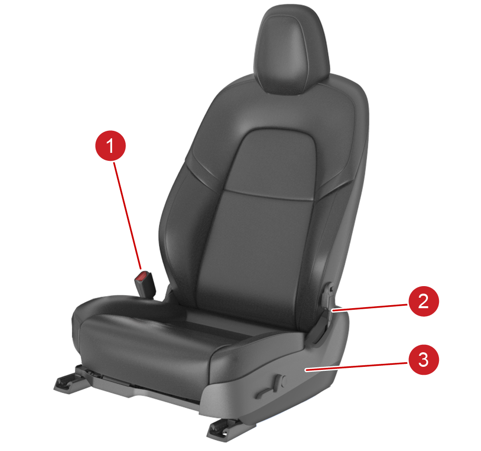
| 1. Buckle 2. Pretensioner 3. Side Shield |
| Safety Seat Components |
 |
|---|
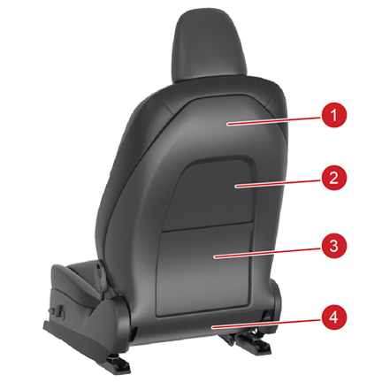
| 1. Seatback panel 2. Seatback insert 3. Seatback pocket 4. Toe kick |
| Rear Seat Plastics |
 |
|---|
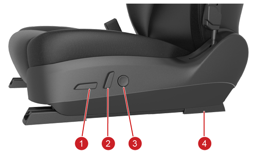
| 1. Seat cushion button 2. Recliner button 3. Lumbar button 4. Track cover |
| Outboard Seat Plastics |
Motorslink
Component Descriptionlink
The front seats have the ability to move on 4 axis:
- Track: forwards and backwards, moves the seat closer or further away from the steering wheel.
- Height: up and down, this allows the height of the seat to be taller or shorter.
- Tilt: up and down, this allows the front pan of the seat cushion to be taller or shorter.
- Recliner: forwards or backwards, moves the back rest around the pivot point of the seat.
Each front seat includes an 8-way, plus lumbar, control switch pack which is used to control the different seat adjustment functionalities. The seat heaters for all seats are activated from the center display.
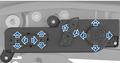 |
|---|
| Seat Controls |
| Action | Button Combo | Resistance (Ohm) | Pin |
|---|---|---|---|
| Up | H | 886 | 1 |
| Down | G | 597 | 1 |
| Forward | F | 1011 | 2 |
| Reverse | E | 676 | 2 |
| Tilt Up | D | 499 | 1 |
| Tilt Down | C | 429 | 1 |
| Backrest Forward | B | 1179 | 2 |
| Backrest Reverse | A | 774 | 2 |
| Lumbar Up | M | 1012 | 3 |
| Lumbar Down | K | 677 | 3 |
| Lumbar Out | J | 774 | 3 |
| Lumbar In | L | 1179 | 3 |
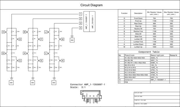 |
|---|
| Circuit Diagram |
Theory of Operationlink
First row seats have a total of four electric 12V DC brushed motors that control the different seat adjustment functionalities. This includes track, lift, tilt, and recline adjustments.
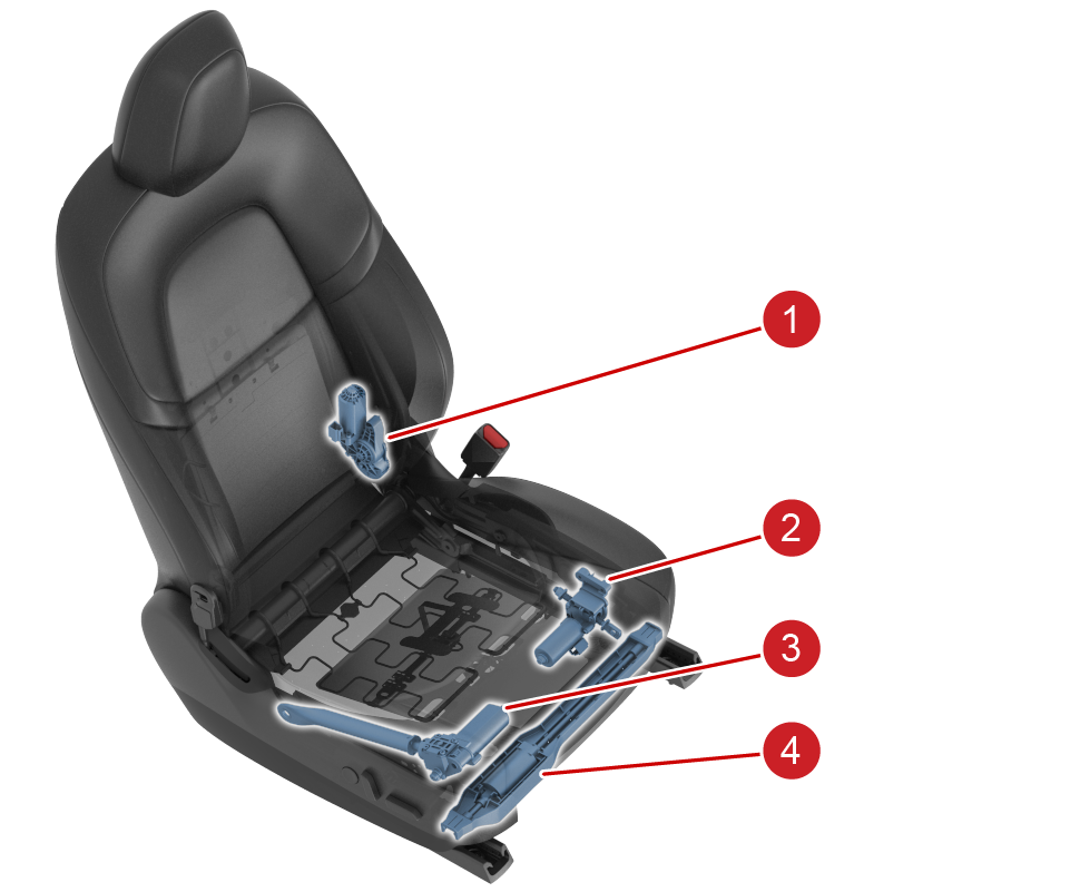 |
|---|
| 1. Recliner motor 2. Tilt motor 3. Height motor 4. Track Motor |
| Motor locations, first row |
|
|---|
| 1. Track, tilt and height control 2. Recliner control 3. Lumbar control 4. Track cover |
| Motor controls |
| Motor | Seat Travel | Encoder Counts per entire range | Travel Time (s) | Nominal Current (A) | Stall Current (A) | Inrush (A) |
|---|---|---|---|---|---|---|
| Track | 260mm | 1242 | 16 | 3 | 12 | 8 |
| Height | 60mm | 2060 | 12 | 6 | 14 | 10 |
| Tilt | ± 3 degrees | 551 | 6 | 3 | 10 | 7 |
| Backrest | ± 20/40 degrees | 2455 | 17 | 5 | 9 | 6 |
Communicationlink
The power functions of the seats are controlled by the left and right body controllers. The left front seat is controlled by VCLEFT and the right front seat is controlled by VCRIGHT.
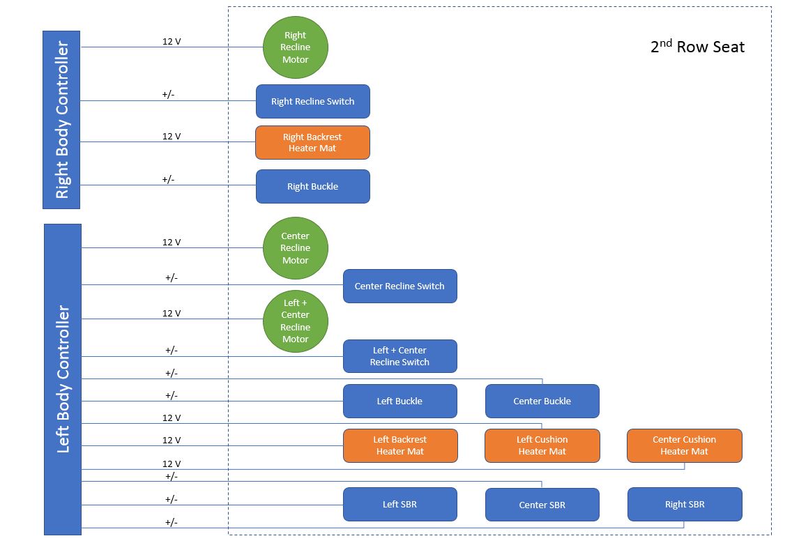 |
|---|
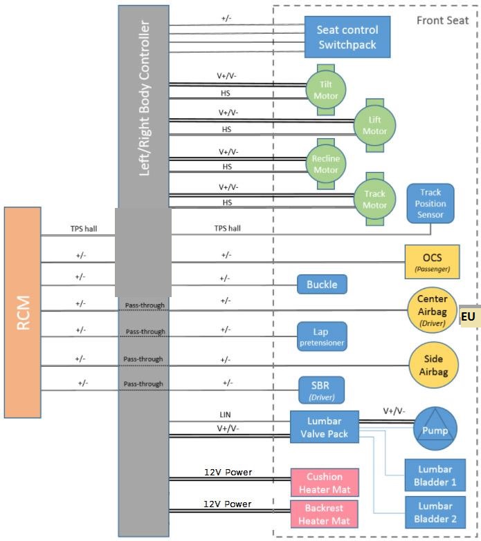 |
Lumbar Support Systemlink
Component Descriptionlink
The Model Y seat lumbar system is a pneumatic 2-bladder, 4-way power system. It consists of an air pump, a valve pack, two air bladders and a lumbar flex mat.
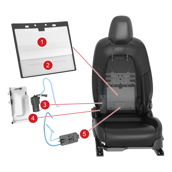 |
|---|
| 1. Bladder 1 2. Bladder 2 3. Pump 4. Foam Pump Bag 5. Valve Pack |
| Lumbar Support System |
Theory of Operationlink
The lumbar control unit is controlled via Local Interconnect Network (LIN) communication by the corresponding left or right body controller. Depending on the user command via the 4-way lumbar control button on the seat, the control unit will pump or deflate the corresponding air bladders to provide the desired lumbar support. The body controller constantly monitors the pressure in each bladder using the pressure sensors in the valve control unit to keep the pressure within specified limits. There is also a blow-off valve for each bladder to release excess air once max pressure is reached.
The lumbar 4-way control button has the controls:
- Up = Inflate (B1), Deflate (B2)
- Down = Inflate (B2), Deflate (B1)
- Right = Deflate (B1)+(B2)
- Left = Inflate (B1)+(B2)
The following movements are a result of pressing two functions together. The switch below the circular button has 4 different switches so pressing two together result in the following:
- Up+Right = Deflate (B2)
- Up+Left = Inflate (B1)
- Down+Left = Inflate (B2)
- Down+Right = Deflate (B1)
Serviceabilitylink
The body controller monitors pressure change during operation to identify a possible leak in the system. If the bladder has a leak or cannot maintain pressure, this could result in failure to calibrate.
Driver Profilelink
Feature Descriptionlink
The Model Y has the ability to save the preferred seating position of the driver. When the driver's seat, steering wheel or driver's side mirror is adjusted, the touchscreen will prompt the customer to create a driver profile to save these adjustments. The driver's profile can utilize the "Use Easy Entry" checkbox if the customer would like the steering wheel and seat to adjust when the park gear is engaged and the driver's seat belt is unbuckled, allowing an easy exit from the vehicle. When returning to the vehicle and stepping on the brake pedal, settings automatically adjust back to the setting used by the most recent driver profile. Model Y supports up to 10 driver profiles. The driver profile can be linked to keys, including authenticated phones, key cards and up to 4 key fobs.
Theory of Operationlink
Model Y Driver's profile is recalled from the UI. When a customer saves a driver's profile it is associated with an index. The UI then saves the orientation of the various motors in mm and degrees. There is then an app layer on VCLEFT which performs inverse kinematics that translates the mm and degrees into encoder counts on the motor.