Controllers and Harnesseslink
Last updated: December 05, 2023
Overviewlink
The vehicle features several controllers and connectors. To focus on reducing the number of devices through consolidation, the main vehicle controllers on Cybertruck are different microcontrollers on the same Printed Circuit Board (PCB). Due to the vehicle's off-roading capabilities, there are additional restrictions to keep in mind when working with the controllers and harnesses to maintain electrical integrity in harsh environments. The main restrictions are the following:
- Avoid back probing any harness connectors below the dash. Back probing these connectors may cause damage to the connector seals which are needed for wading through water without water ingress. As alternatives for back probing:
- The super connectors have front probing points for measurements
- Inline service harness for select connectors are available to make live measurements
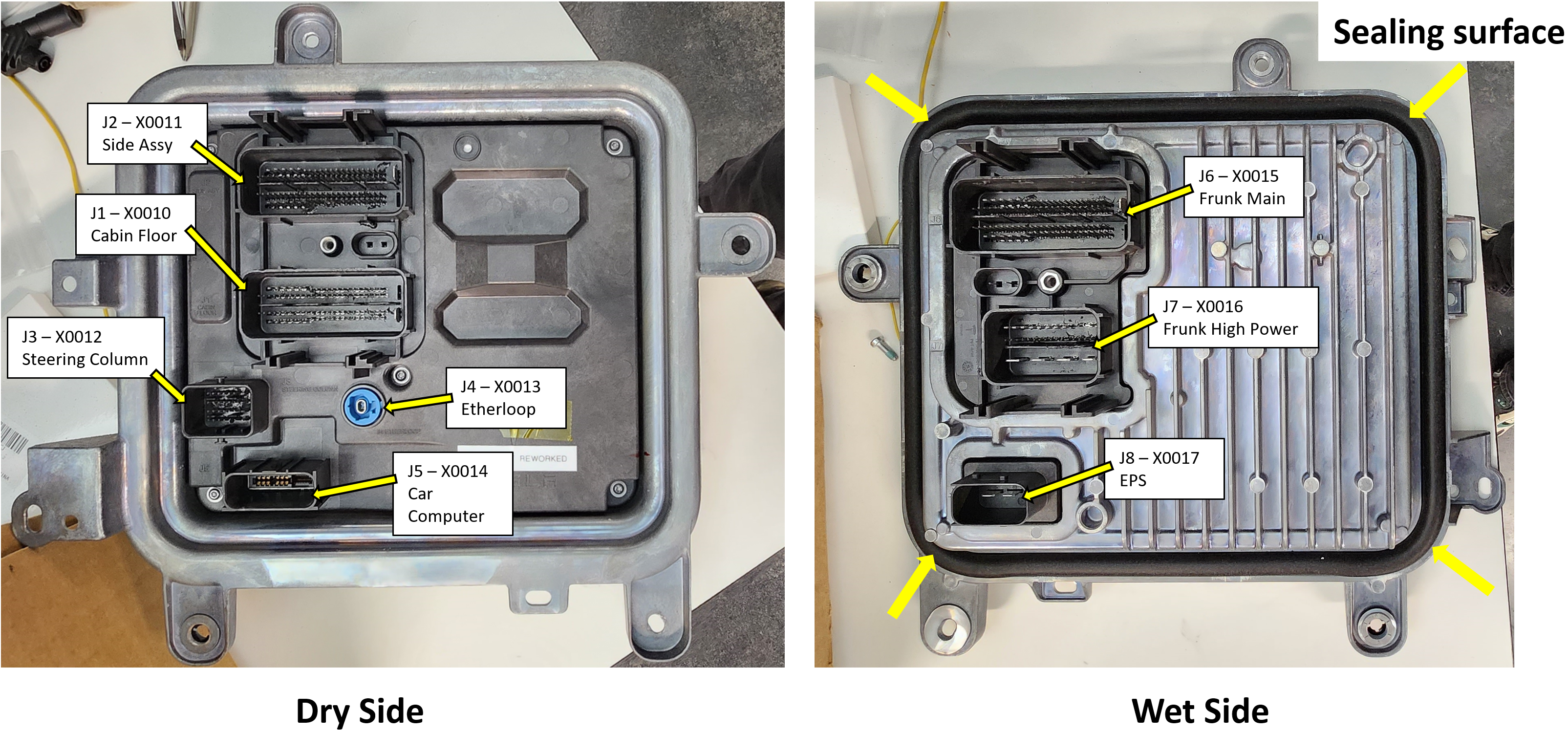
- The Left Controller and Right Controller both act like a passthrough for the harness to go between a wet side and dry side. Both of these controllers have seals on their surface. Care needs to be taken when mounting or removing these controllers to not damage these seals.
Arcing Risklink
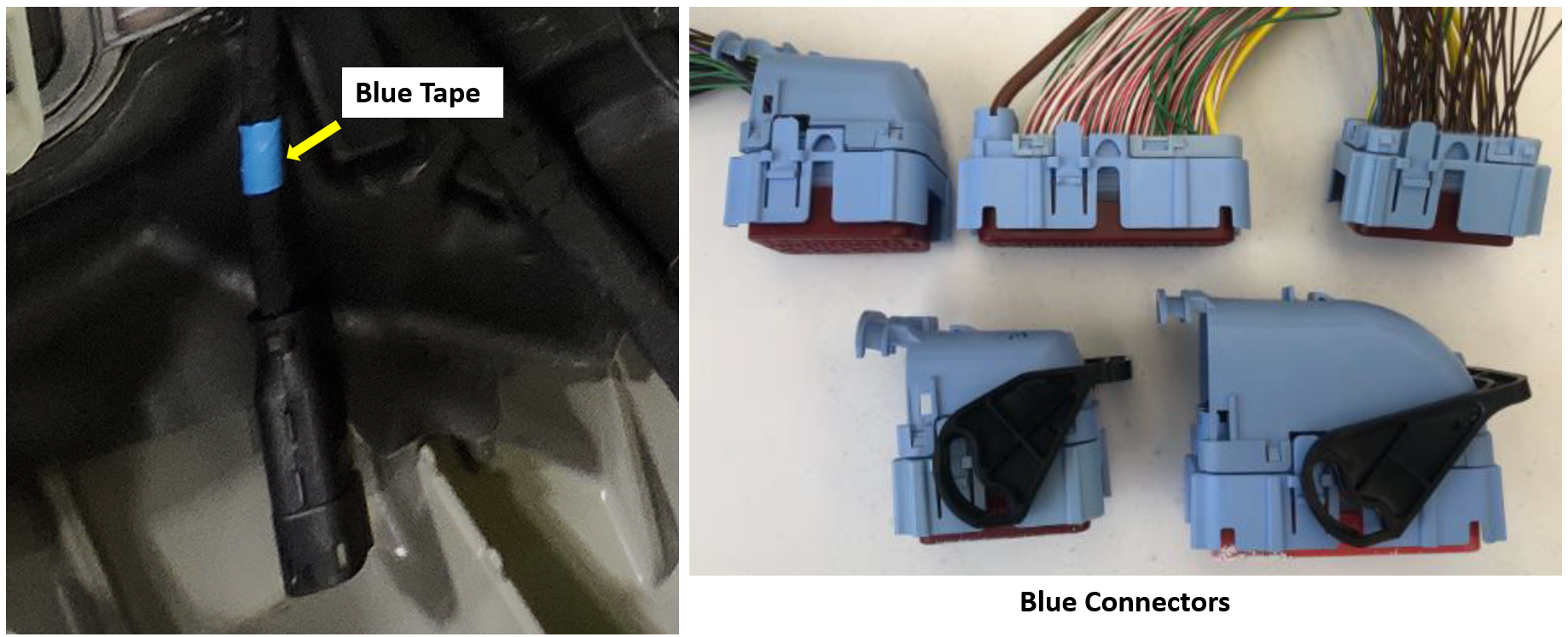
The vehicle features a Mid-Voltage (MV) architecture with a typical voltage range of 43 - 48V. All electrical buses need to be treated with appropriate caution. However, because Mid Voltage circuits operate at a higher potential than traditional low voltage (9V-16V), they carry an increased risk of component damage, harness damage, or personal injury when misused. Always use proper Personal Protective Equipment (PPE) and caution when investigating the MV system. To preserve connector integrity, do not disconnect or connect circuits while MV is enabled. All connectors carrying MV will either be blue or will have blue tape on the harness to indicate it is a MV connector.
 |
|---|
| Example of Blue Designations of Connectors and Harnesses |
Warning
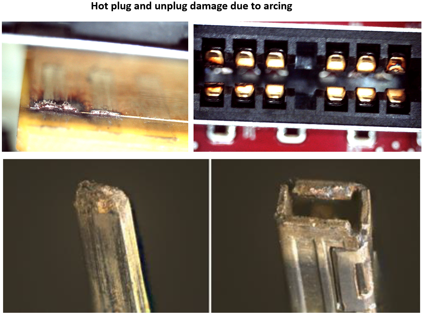
Do not carry out any live disconnections or live mating of any MV connections. If ignored, this will result in arcing that can cause: - Personal injury. - Immediate damage to components, connectors, or harnesses. - Damage to terminal coatings that will lead to corrosion and eventually, loss of core vehicle function.
Note
The first responder loop connector is the only connector with mid voltage that is allowed to be disconnected while the vehicle is powered.
 |
|---|
| Some Effects of Live Disconnections or Live Mating |
Controllerslink
Cybertruck features three primary mid-voltage (MV) controllers - Left controller, Right controller, and Rear controller.
Grounding Strategylink
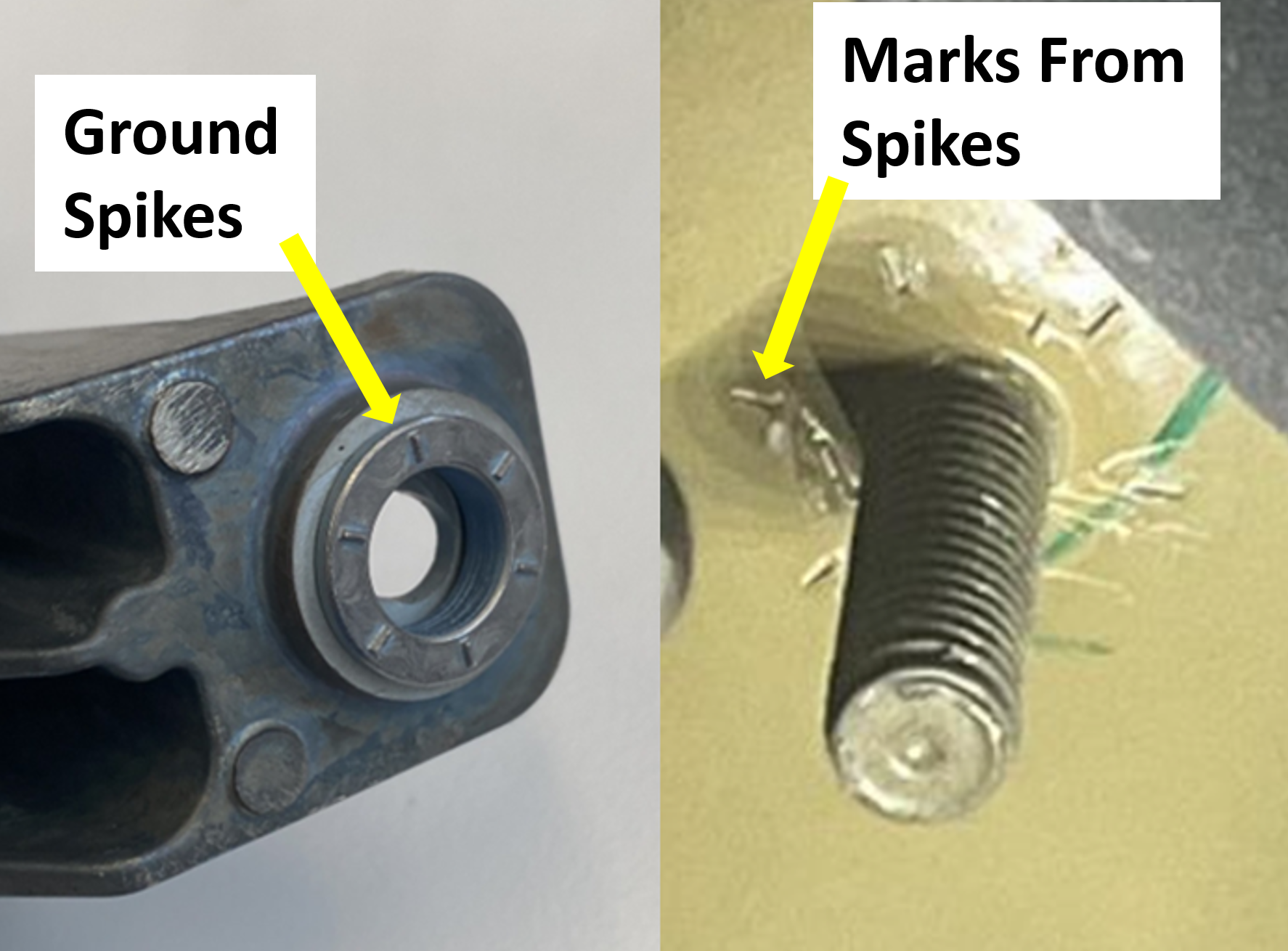
These controllers are grounded to the MV power source via the vehicle chassis. Each of the controllers have ground spikes at the bottom; these spikes are designed to push through the ecoat to ground the controller.
Warning
Failure to follow the controller mounting torque spec will result in:
- Water ingress to the dry side due to seal not having the correct mounting force for left controller and right controller.
- High resistance on the grounding path for left, right, and rear controller. This can result in component damage and loss of core functionality.
Important
Follow the controller mounting torque even while testing. This is required to ensure the controller receive a good ground connection.
 |
|---|
| Ground spikes and witness marks |
Precharge for Mid-Voltage Endpointslink
Higher voltages of Mid-voltage (MV) system in comparison to Low Voltage (LV) can result in high inrush currents when eFuses are closed. The inrush current is bad for eFuse and the downstream endpoints. To alleviate this issue, controllers use a precharge circuit to reduce the inrush current to an acceptable value.
| Controller | Precharged endpoints |
|---|---|
| Left Controller | • Autopilot • Door Controller Front Left • Door Controller Rear Left • Electronic Power Steering • Media Control Unit (MCU) • MV Bridge • Steering Feedback Actuator • Switched Tank Converter (STC) |
| Rear Controller | • PCS • Rear Steering Controller • Trailer controller |
| Right Controller | • Autopilot • Auxilary Power Frunk • Auxilary Power Roof • Door Controller Front Right • Door Controller Rear Right • Electronic Power Steering • Media Control Unit (MCU) • MV Bridge • Rear Controller • Steering Feedback Actuator • Supermanifold Controller |
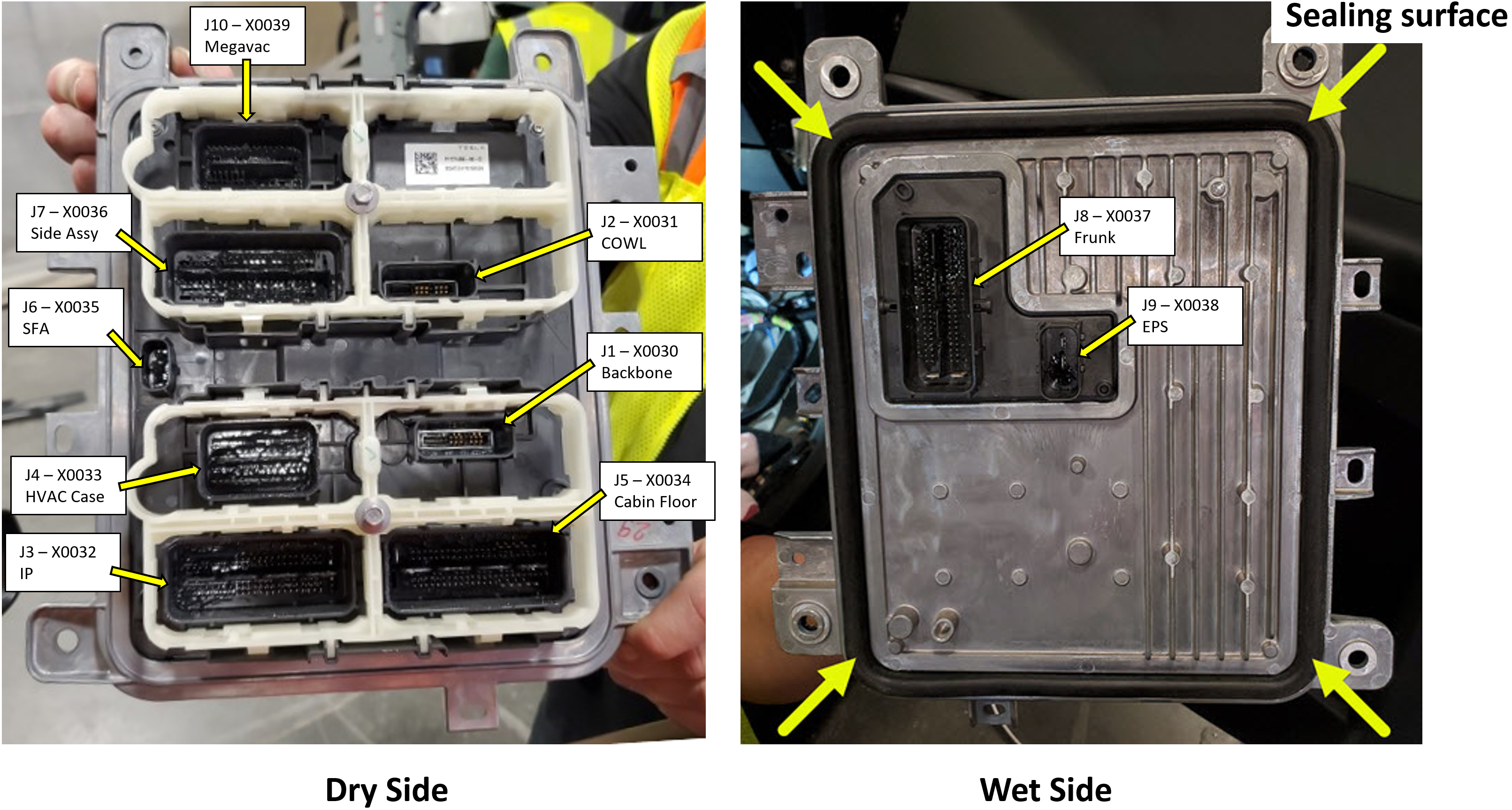
Left Controllerlink
The Left Controller is the primary control for managing the vehicle's state. It is part of the left power domain, and its primary power source is the Mid Voltage (MV) battery. It has a Low Voltage (LV) bridge running to the Right Controller to allow charging through the Power Conversion System (PCS) and to support all Low or Mid-Voltage loads on the vehicle.
The front trunk (frunk) access post and vehicle jump post are directly connected to the left controller.
 |
|---|
| Left Controller Wet and Dry Sides |
The following controllers are consolidated into the left controller PCB:
- Left Vehicle Controller (VCLEFT)
- Left Electronic Parking Brake (EPBL)
- Electronic Park Brake Monitor Left (EPBM)
- Vehicle Security Controller (VCSEC)
- Mid-Voltage Battery Management System (LVBMS)
- Pedal Monitor (PM)
- Drive Interface Master (DI)
- Left Amplifier
- Air suspension (TAS split into VCREAR, VCRIGHT, and VCLEFT with VCREAR as leader)
- Left Etherloop Generalized Gateway (EGGLEFT)
Left Controller Power Distributionlink
VCLEFT is responsible for controlling power to the left domain of the vehicle. It uses eFuses and H-bridges to control the power of downstream devices.
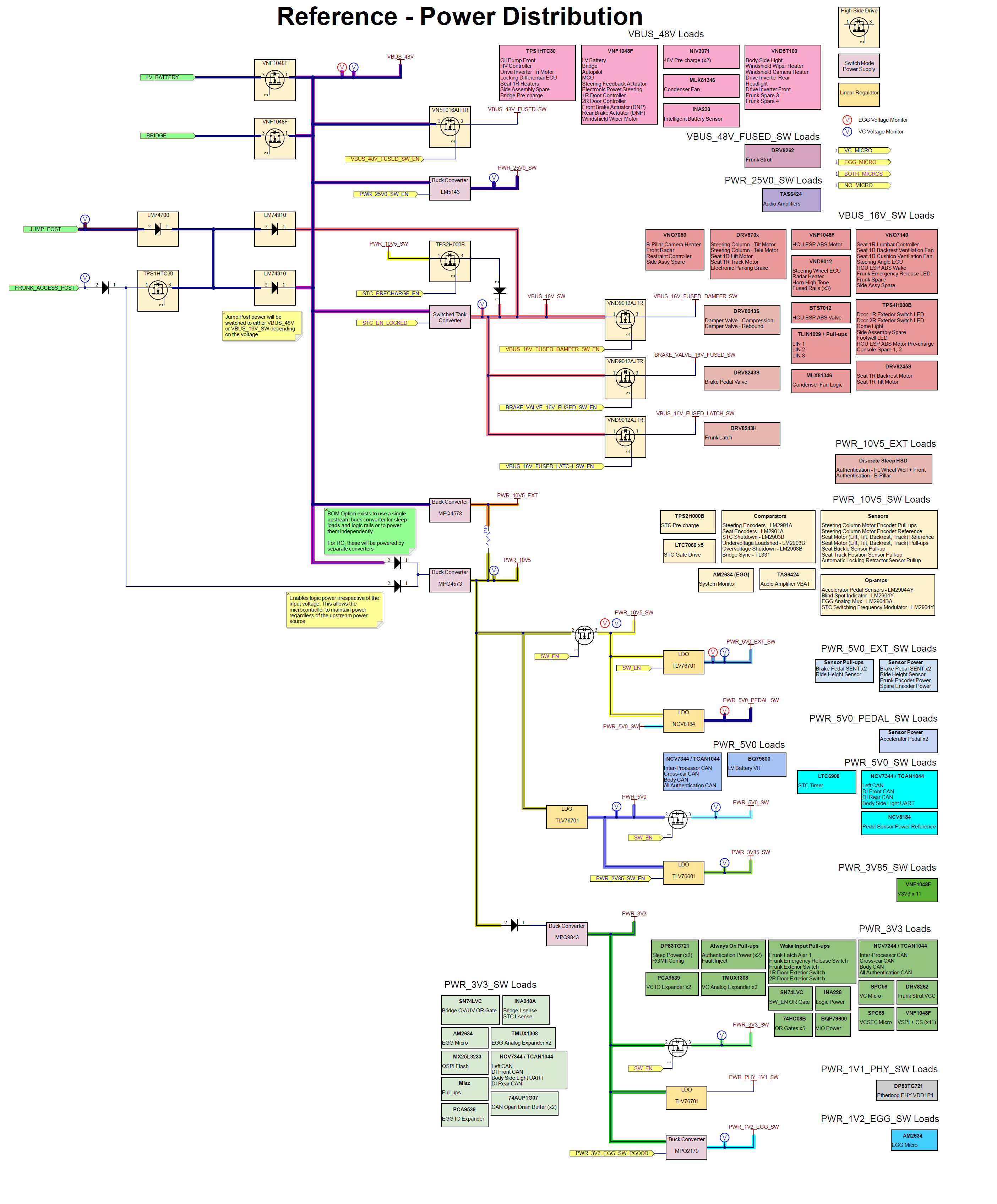 |
|---|
| Left Controller Power Distribution Architecture |
Right Controllerlink
The Right Controller controls the right power domain of the vehicle. It has a Low Voltage (LV) bridge running to the Left Controller for allowing charging through the Power Conversion System (PCS) and supporting all Low or Mid Voltage loads on the vehicle. Right controller connects to the Rear Controller via the backbone cable that carries power and communication lines.
 |
|---|
| Right Controller Wet and Dry Sides |
The following controllers are consolidated into the right controller PCB:
- Right Vehicle Controller (VCRIGHT)
- Right Amplifier
- Air suspension (TAS split into VCREAR, VCRIGHT, and VCLEFT with VCREAR as leader)
- Right Etherloop Generalized Gateway (EGGRIGHT)
Right controller Power Distributionlink
Right controller is responsible for controlling power to the right domain of the vehicle. It uses eFuses and H-bridges to control the power of downstream devices.
| Description / Function | Bus |
|---|---|
| BLE Anchors | 10.5 |
| Interior Radar | 10.5 |
| Overhead Gear Shift | 10.5 |
| VCREARP 1.uC (NW, BC, EPBM, WSS, TAS, Susp) | 16 |
| Side Marker RL | 16 |
| Side Marker RR | 16 |
| CP Charge Port Controller | 16 |
| DFLKR Controller Diff.Lock Rear | 16 |
| License Lamp | 16 |
| VCREARS 2.uC (BC,LVPM,EPB) | 16 |
| SW,Buckle,RL | 16 |
| SW,Buckle,RR | 16 |
| SW,Buckle,RC | 16 |
| Susp.Accel. RL | 16 |
| Susp.Accel.RR | 16 |
| Act,Rel,Armrest,2R | 16 |
| Ride Height RL | 16 |
| Ride Height RR | 16 |
| Latch,Tailgate,LH | 16 |
| Latch,Tailgate,RH | 16 |
| SW,Occup.,RL | 16 |
| SW,Occup.,RR | 16 |
| Thermistor RL | 16 |
| Thermistor RR | 16 |
| Valve,Damper RL | 16 |
| Valve,Damper RR | 16 |
| Reverse Lamp LH | 16 |
| Reverse Lamp RH | 16 |
| LED,Ext.DoorSW,RR | 16 |
| Susp.Comp.Valves | 16 |
| Auth. Endpoint Wheel Well RR | 16 |
| Auth.Endpoint Wheel Well RL | 16 |
| Auth. Endpoint Tonneau/Tailgate | 16 |
| EPB Caliper Right | 16 |
| Suspension Master Valve Block | 16 |
| SW,Tailgate | 16 |
| SW,Tonneau | 16 |
| Rear Amp | 26 |
| Speaker - Pedestrian Warning, Rear Fascia | 26 |
| Aux Stop (CHMSL) | 48 |
| Body StopTurn RR | 48 |
| Body Tail RR | 48 |
| Tail Light Cross-car + CHMSL | 48 |
| VIPR base | 48 |
| Trailer Controller | 48 |
| Body Side Tail Lamp RL | 48 |
| Body Side Tail Lamp RR | 48 |
| VIPR uC | 48 |
| Tonneau Cover Motor Left | 48 |
| Tonneau Cover Motor Right | 48 |
| Aux Tail Lamp | 48 |
| Rear Steering Controller | 48 |
| Heat Back RL | 48 |
| Heat Back RR | 48 |
| Suspension Compressor | 48 |
| VIPR HV Wireless Charger | 48 |
| Light,Bed,LH | 48 |
| Light,Bed,RH | 48 |
| Heat Cush. RL | 48 |
| Heat Cush. RR | 48 |
Rear Controllerlink
The Rear Controller is part of the right power domain, and its primary power source is the Power Conversion System (PCS). Rear controller connects to right controller via the backbone cable that carries power and communication lines.
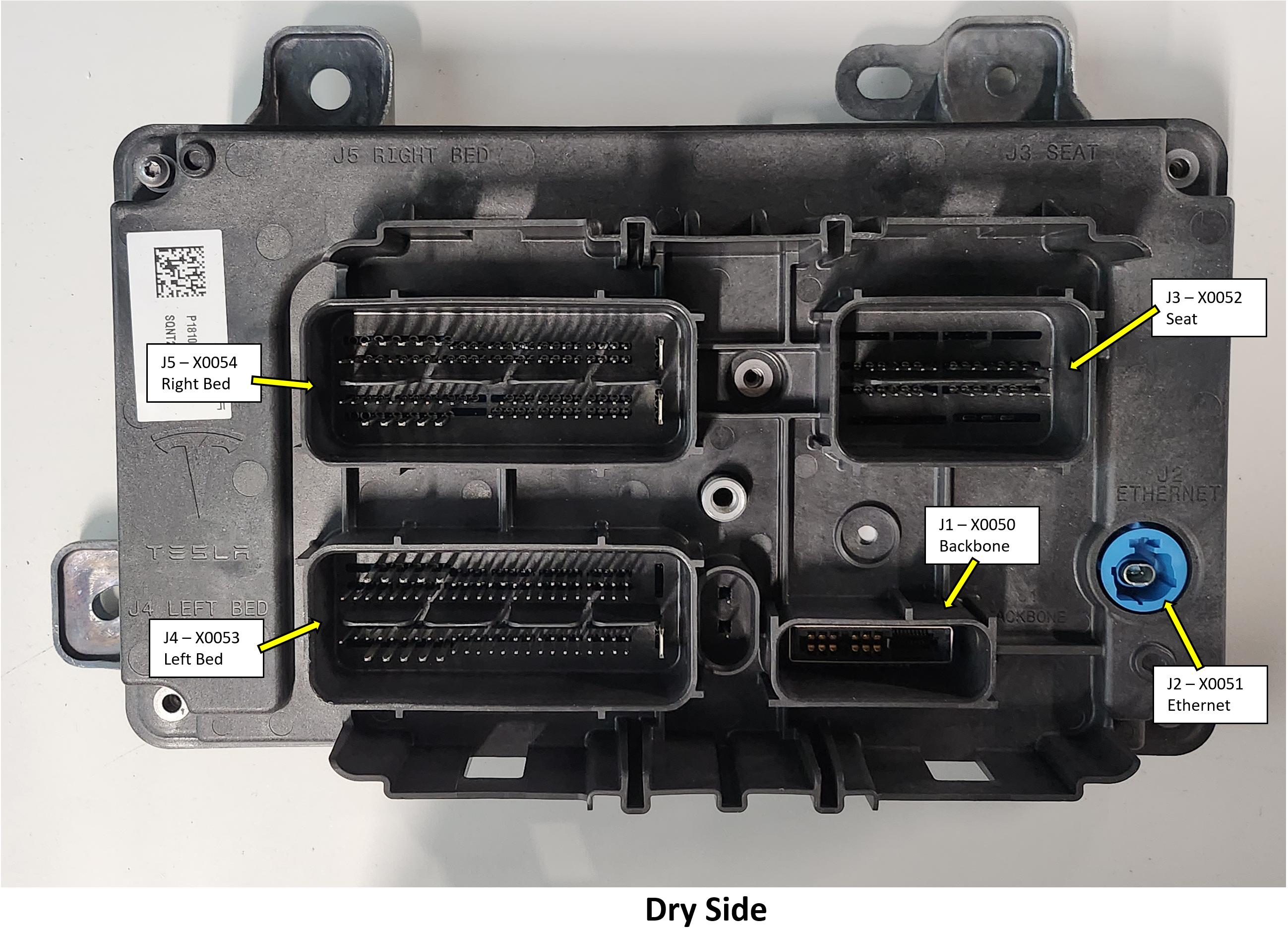 |
|---|
| Rear Controller Dry side |
The following controllers are consolidated into the rear controller PCB:
- Rear Vehicle Controller (VCREAR)
- Right Electronic Parking Brake (EPBR)
- Right Electronic Parking Brake Monitor (EPBM)
- Rear Amplifier
- Air suspension (TAS split into VCREAR, VCRIGHT, and VCLEFT with VCREAR as leader)
- Rear Etherloop Generalized Gateway (EGGREAR)
Rear controller Power Distributionlink
Rear controller is responsible for controlling power to the rear half of the vehicle. It uses eFuses and H-bridges to control the power of downstream devices.
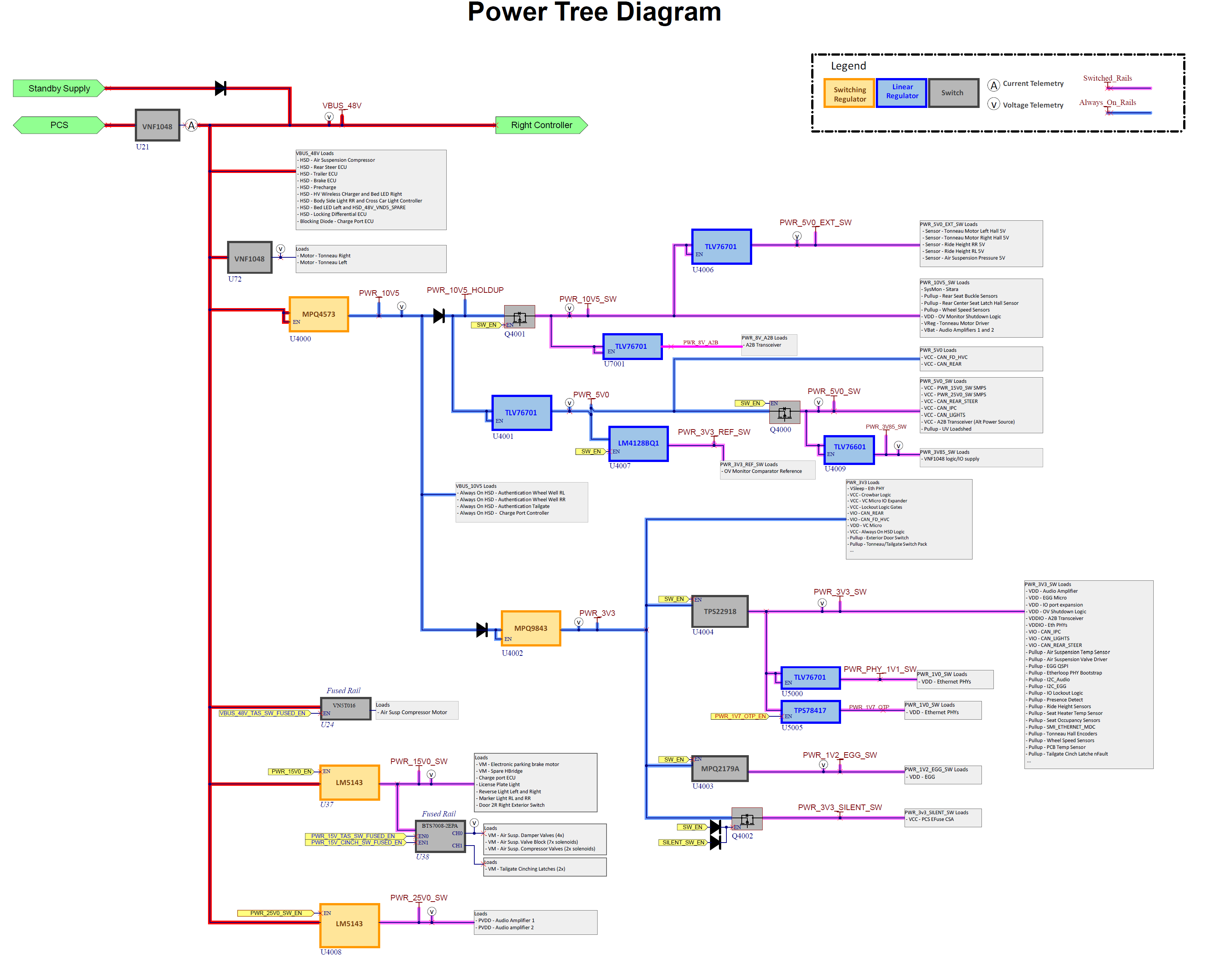 |
|---|
| Rear controller Power Distribution Architecture |
Special Connectorslink
The Mid-Voltage (MV) system introduces a new design for connectors called Super Connectors. Most of the large, blue connectors throughout the vehicle are a Super Connector variant.
Super Connector with Locking Coverlink
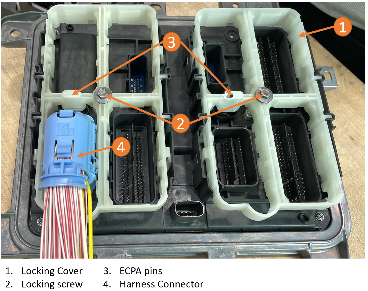
Super Connector uses a locking cover and locking screw as a Connector Position Assurance (CPA).
Important
It is important to follow the locking cover torque spec. Failure to do so will result in connectors being soft set.
 |
|---|
| Super Connector with Locking Cover |
When the locking screw is rotated in a clockwise direction, it pushes the locking cover down, which pushes the harness connectors into the controller slots. When the screw is torqued to specification value, the harness connectors are fully engaged.
Conversely, when the locking screw is rotated in a counterclockwise direction, it lifts the locking cover which pulls the harness connectors out of the cavities. When the locking screw is free spinning, the harness connectors are fully disengaged.
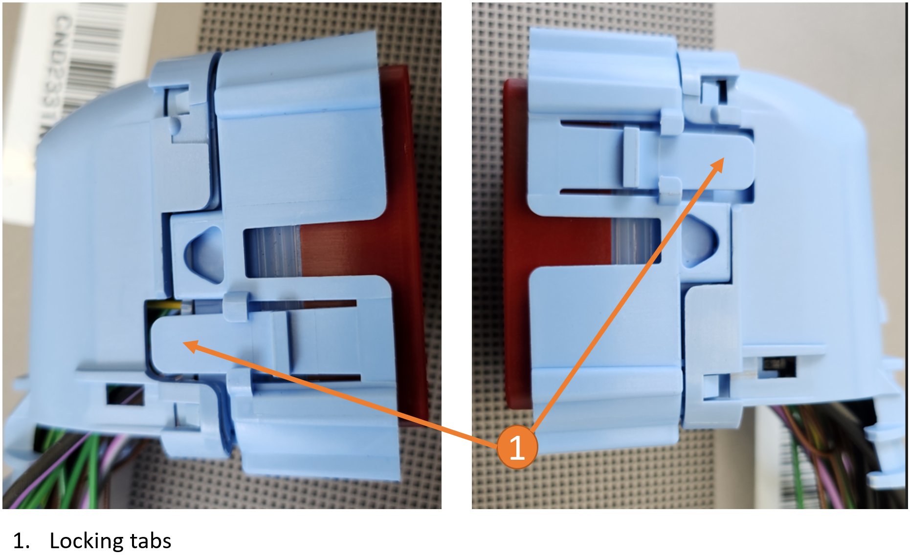
Harness connectors can be removed from the locking cover by pressing the locking tabs and pulling the connector out.
Important
It is advisable to utilize a power tool such as an impact wrench for efficient removal of the locking cover. The increased speed of the tool aids in achieving a smooth disconnection. When securing the locking cover, it is advisable to gradually engage it using a powered tool and subsequently employ a torque wrench to confirm the final torque of the locking screw.
 |
|---|
| Super Connector Locking Tabs |
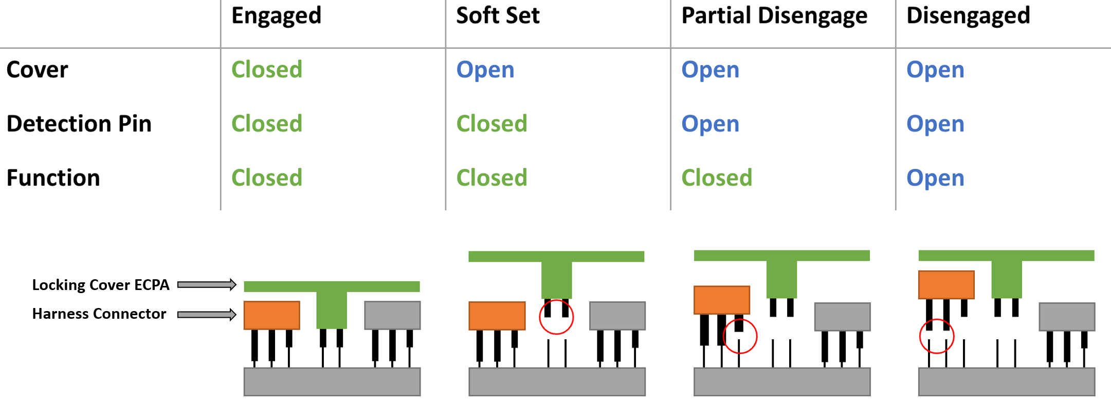
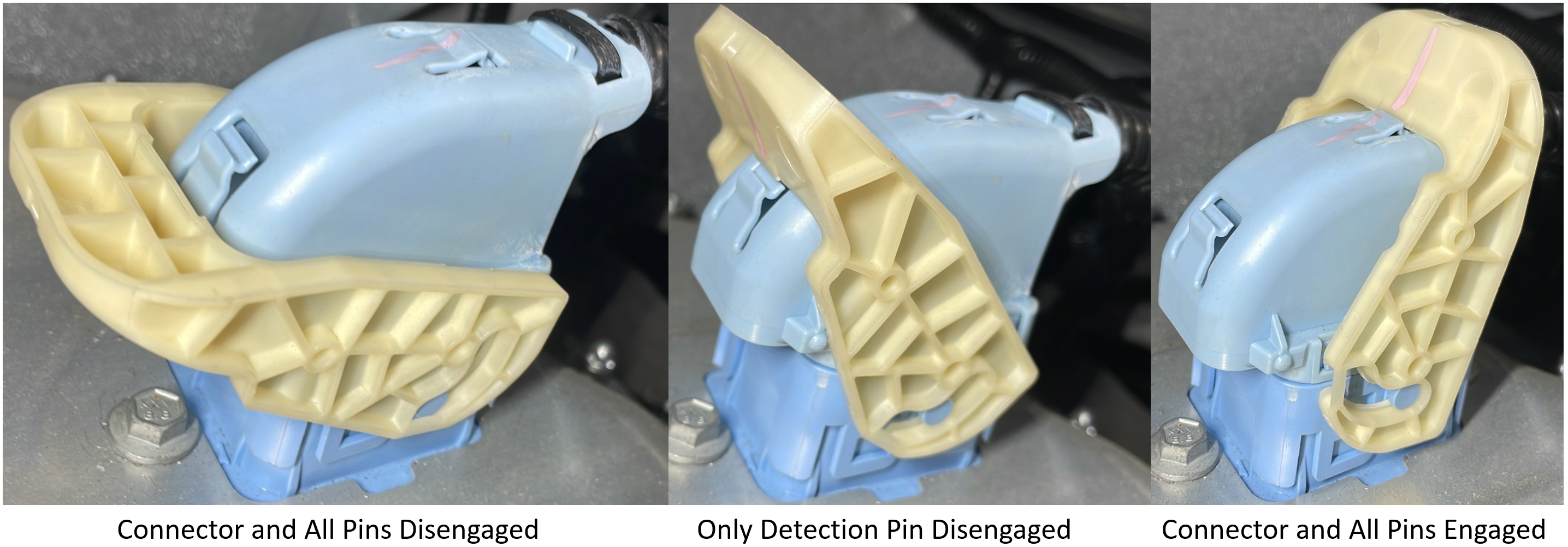
Each of the locking covers have Electronic Connector Position Assurance (ECPA) pins. These pins help controllers determine whether the locking cover is fully engaged. If the vehicle controller does not detect position assurance, then it reports an alert indicating the locking cover is soft set. Each of the harness connectors also have a detection pin that is shorter than other pins. This detection pin disengages before other pins when the connector is being disconnected. The vehicle controllers are able to detect when the detection pin is disengaged and sets an alert for this condition.
 |
|---|
| ECPA Logic Table |
| Signal | Description | Controller | Location |
|---|---|---|---|
| VCLEFT_a543_connectorCoverFault | Locking cover is soft set | VCLEFT | Look at payload data |
| VCRIGHT_a543_connectorCoverFault | Locking cover is soft set | VCRIGHT | Look at payload data |
| VCREAR_a543_connectorCoverFault | Locking cover is soft set | VCREAR | Look at payload data |
| VCLEFT_a545_connectorFaults | Harness connector is soft set | VCLEFT | Look at payload data |
| VCRIGHT_a545_connectorFaults | Harness connector is soft set | VCRIGHT | Look at payload data |
| VCREAR_a545_connectorFaults | Harness connector is soft set | VCREAR | Look at payload data |
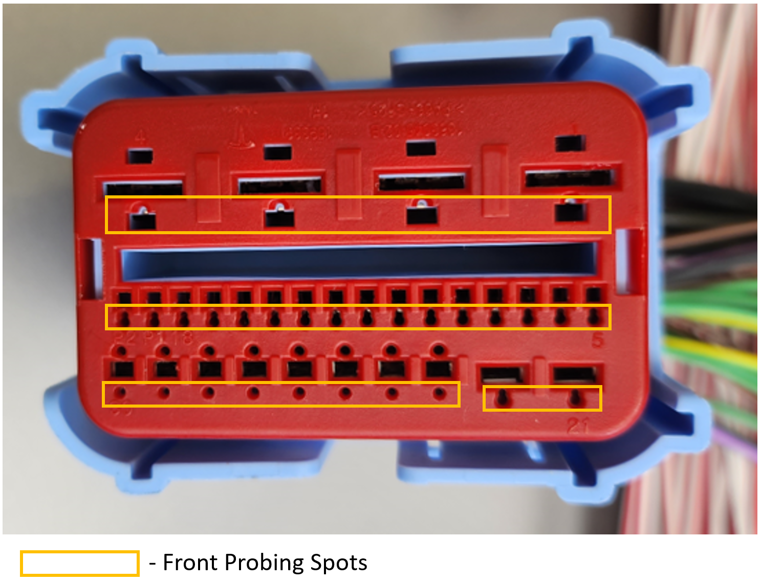
Since back probing the Super Connectors is not advised, these connectors have front probing areas that can be used without damaging the pins. When looking at the front face of the connector, there are three cavities per pin:
- Cavity for the pin
- Larger cavity for de-pinning
- Smaller cavity for front probing
 |
|---|
| Front Probing Cavity Locations |
Super Connector with Locking Leverlink
Some Super Connectors variants use a locking lever instead of a locking cover and locking screw to keep the connector engaged.
These connectors have a detection pin that is shorter than other pins. This detection pin disengages before other pins when the connector is being disconnected. Controllers are able to detect when the detection pin is disengaged and will set an alert to indicate this condition.
 |
|---|
| Super Connector with Locking Lever |
Tesla Scalable Power (TSP) Connectorslink
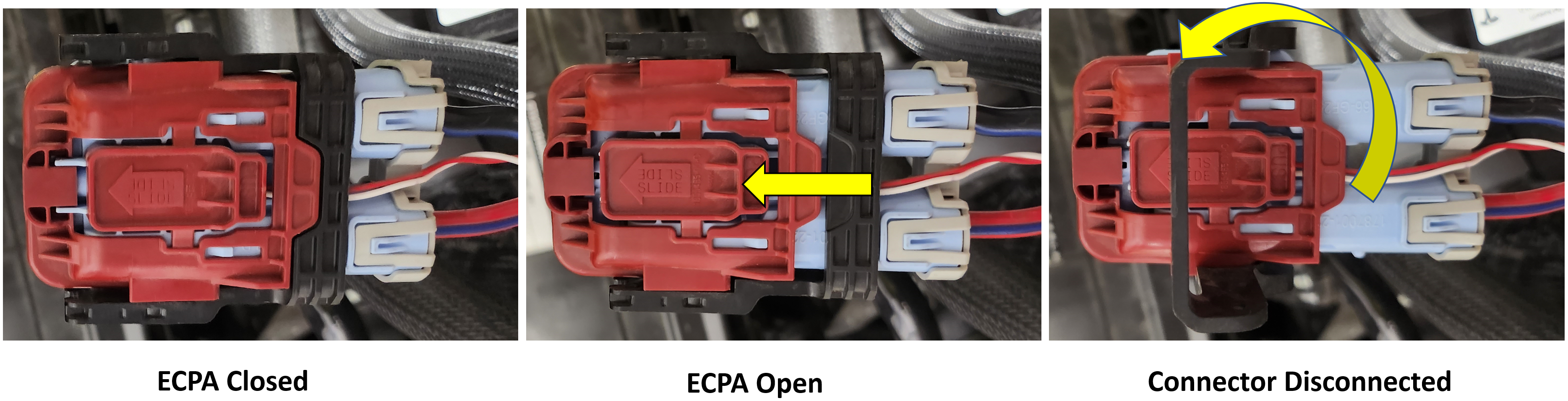
Tesla Scalable Power (TSP) connectors are designed to support a larger variety of voltages. Specifically, the vehicle uses these connectors for the Power Conversion System (PCS) and Mid Voltage (MV) battery. These connectors have an Electronic Connector Position Assurance (ECPA) lock and a locking lever to engage / disengage the connector.
 |
|---|
| Tesla Scalable Power Connector |
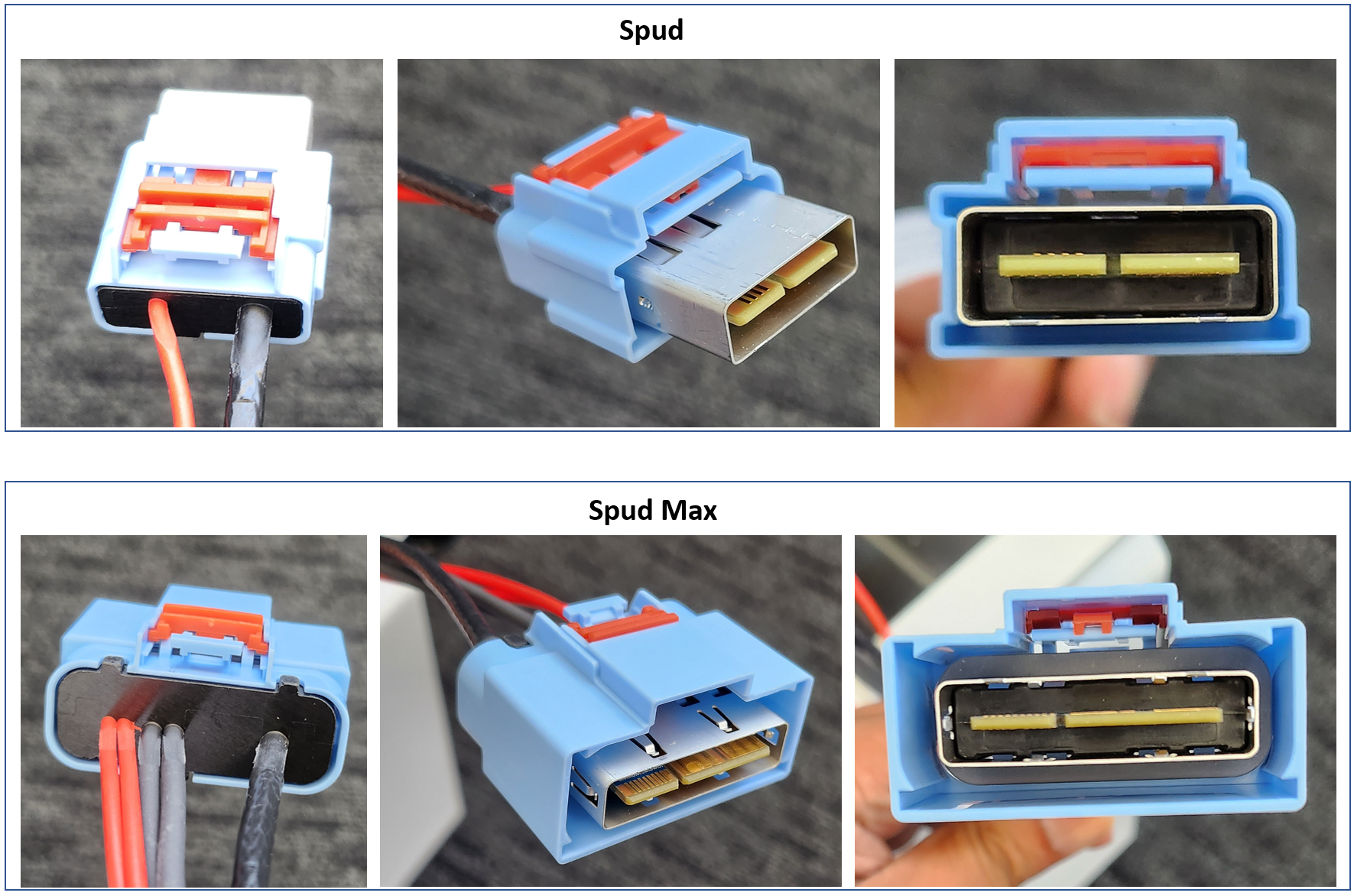
Spud and Spud Max Connectorslink
The Spud and Spud Max connectors do not use traditional pin terminals. Spud Max and Spud are on the same sub-harness that connects VCRIGHT and the car computer. They both carry power and communication. These connectors have a detection pin that is shorter than other pins. This detection pin disengages before other pins when the connector is being disconnected. Vehicle controllers are able to detect when the detection pin is disengaged and will set an alert to indicate this condition.
Note
Spud and Spud Max connectors cannot be back probed or front probed.
 |
|---|
| Spud and Spud Max Connectors |
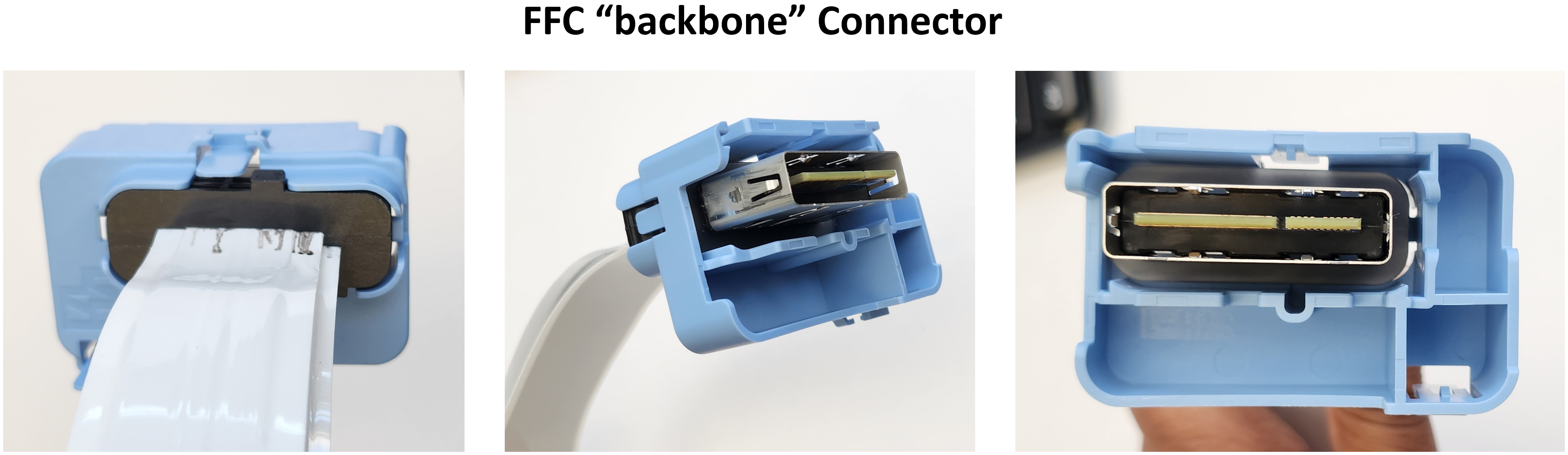
Flat Flexible Cable (FFC) Backbone Connectorlink
A Flat Flexible Cable (FFC) is a thin, bendable electrical cable consisting of parallel flat conductive strips encased in flexible insulation. These enable cost reductions in connector cost, harness weight, and simplify the connection between the front and rear of the vehicle. The vehicle uses a FFC to connect the rear controller to the right controller. This FFC harness connection is also called the "backbone" connector. Power and communication between rear controller and right controller is transmitted by this FFC backbone connector.
Note
The Flat Flexible Cable (FFC) harness and connectors cannot be front or back probed.
 |
|---|
| FFC Backbone Connector |
Powering and Controlling Connected Loadslink
Powering Loadslink
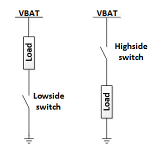
The Mid-Voltage (MV) vehicle controllers use integrated circuits, an H-Bridge, and a high-side driver to control the flow of power to the various loads connected to the vehicle controllers.
High-Side Driverlink
A high-side driver is a transistor switch which can turn power to a downstream load ON and OFF. When the switch is ON, battery voltage is applied to the load. The current that flows depends on the load. When the high-side driver is ON, it does not affect the current. Many high-side drivers feature a current sense inside the switch and turn off automatically in an over-current event. A high-side driver that turns off when a specific current level is reached is called an eFuse.
Note
For more information on eFuses, refer to eFuses.
 |
|---|
| High-Side Driver vs. Low-Side Driver |
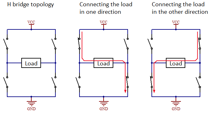
H-Bridgelink
An H-Bridge is a circuit which can apply voltage across a load in two directions. It is commonly used for controlling DC brushed motors since both directions of current flow will spin the motor in different directions. Some examples of DC motors controlled in this way are motors in the seat, steering column, and window lift.
Note
When probing the pins for an H-Bridge, make sure to measure across the two pins of the load. If measured from one of the H-bridge pins to ground, the readings may not match what the load is seeing.
 |
|---|
| H-Bridge |
Harnesses and Passthroughslink
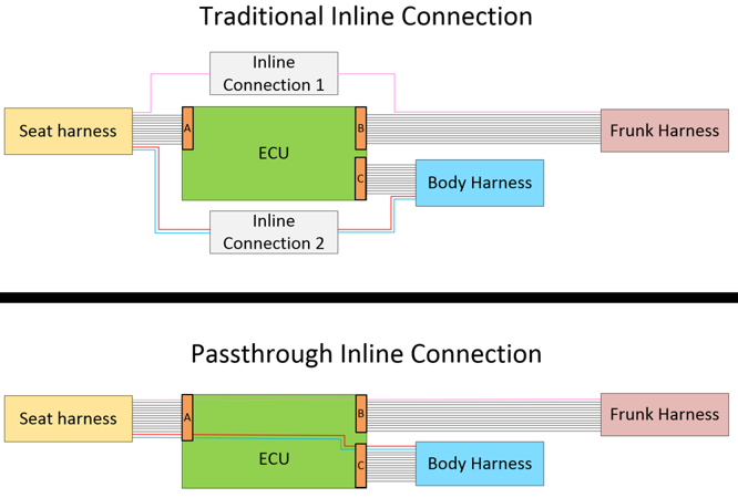
In addition to the use of traditional harnesses, there are also passthrough connections used to reduce the number of the inline connectors and wire splices required to connect the controllers in the vehicle.
A passthrough connection is a metal trace on a Printed Circuit Board (PCB) at one of the vehicle controllers and acts like a wire harness extension. This trace does not touch any other circuitry on the Printed Circuit Board (PCB). It is just treated as a wire.
Example of a passthrough vs. traditional inline connector:
- Using traditional inline connectors, the design requires connectors A, B, and C along with inline connectors 1 and 2.
- Using passthroughs, the design only requires connectors A, B, and C. Inline connectors 1 and 2 are not required.
 |
|---|
| Traditional Inline Connectors vs. Passthroughs |
Note
For more information on CAN and vehicle communication architecture, see Communication Architecture.
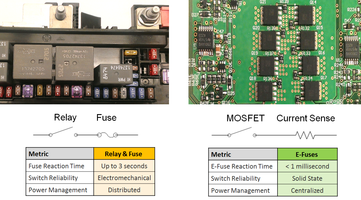
eFuseslink
eFuses Overviewlink
An eFuse is a solid state switch / transistor and a current sensor. When the current through the transistor exceeds firmware or hardware limits, the switch quickly opens. The eFuse replaces the traditional relay and fuse combination and allows for better handling of electrical conditions and protection of harnesses if a condition affecting the MV system is present. Traditional fuses can take several seconds to trip while an eFuse can interrupt current flow in milliseconds. To use eFuses, detailed electrical behavior for each load is required to differentiate between a false positive and a true condition. Significantly impacting the concept of power rails, eFuses allow for firmware-controlled virtual grouping of individual eFuses into virtual power rails, which are referred to as vehicle states.
Note
The vehicle has no traditional fuses. It is only equipped with eFuses.
 |
|---|
| Traditional Fuse (left) vs. eFuse (right) |
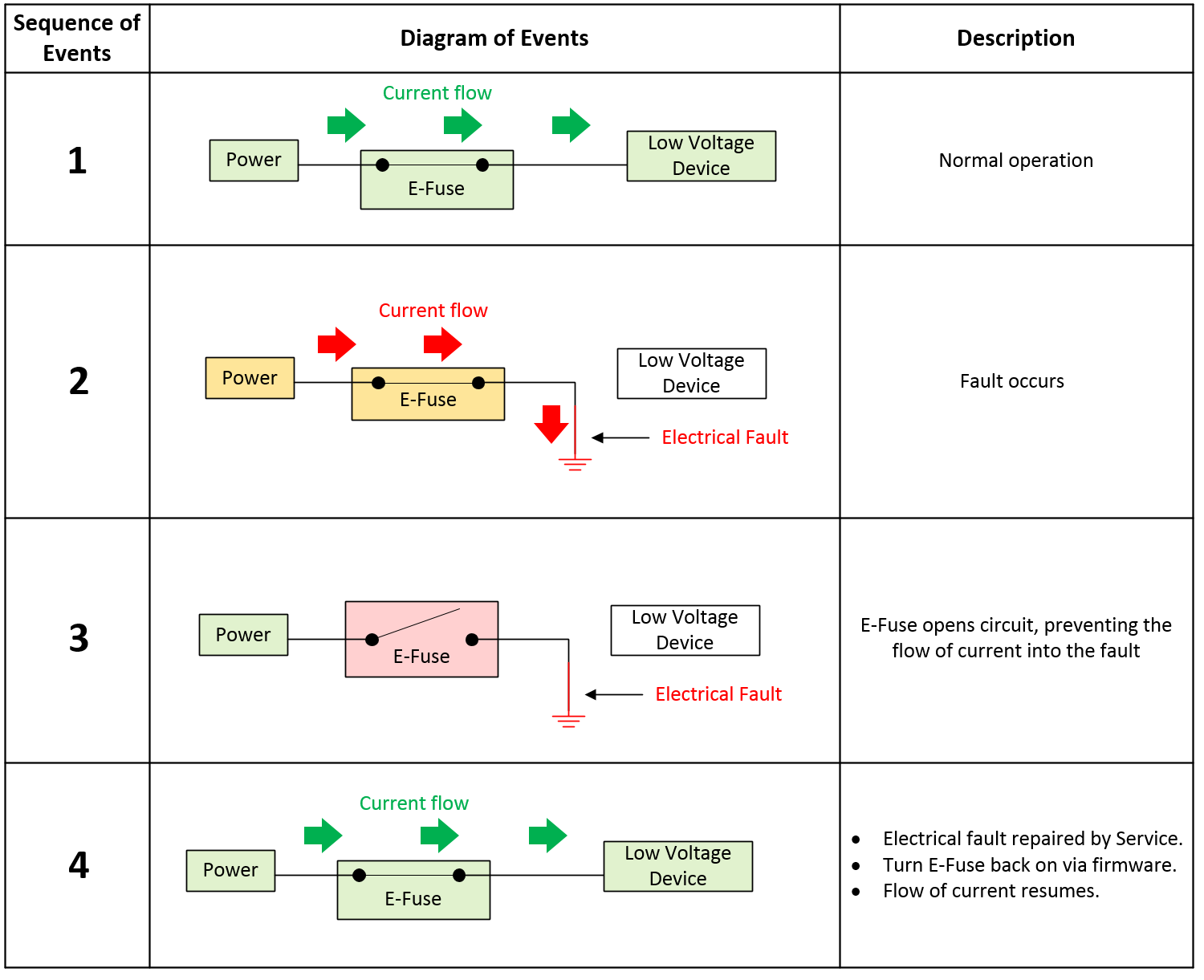
eFuse Operationlink
An eFuse operates like a traditional fuse opening the circuit when a current threshold is exceeded. However, it reacts faster.
 |
|---|
| eFuse Overview |
eFuse Trippinglink
If an eFuse trips, a signal will be read by the microcontroller. Depending on the type of load the eFuse is connected to, the construction of the eFuse, and the vehicle state when the condition is present, the behavior may be to enter either an auto-retry or latch-off mode. Some eFuses may only enter latch-off while some may always enter auto-retry, and some eFuses are configurable. In Tesla vehicles, most eFuses fall under the configurable category.
After an eFuse trips, the firmware does not immediately try to re-enable the eFuse. The design intent is for the eFuse to only trip when an unexpected electrical condition occurs. The eFuse should only be re-enabled after the unexpected electrical condition has been resolved . A few exceptions to this statement exist:
- Capacitive in-rush: In this scenario, the firmware quickly re-enables eFuses to pre-charge downstream capacitive loads.
- User-accessible ports such as the low voltage power socket, USB ports, and trailer lights can be reset by cycling control to those outputs to recover them.
Auto-Retrylink
The intent of auto-retry is to have the firmware intervene when an unexpected electrical condition is detected, using the fault signal sent to the microcontroller, and to immediately disable the eFuse until predefined conditions are met to re-enable the eFuse.
When an eFuse is capable and configured for auto-retry, it will turn off, wait a period of time, then attempt to turn back on for a period of time as determined by the firmware.
Latch-Offlink
When a latch-off eFuse trips, it will turn off and remain off until the firmware resets the eFuse. An eFuse reset is typically achieved by toggling the enable signal OFF to ON. The enable signal will always be reset in the event of a power on reset of the microcontroller, unless the enable line is locked out.
Lock-Outlink
There are specific conditions where the firmware prevents toggling of the enable line via separate protection circuitry. This is only done for eFuses deemed drive-critical, not all eFuses. This is true in the Drive (D) state, where it is unacceptable for the firmware to actively disable any eFuse. This does not mean the eFuse cannot trip, it only means the microcontroller cannot turn off or toggle the eFuse enable signal. This lock-out persists on the vehicle controllers even through a reset of the main microcontroller. The only way to unlock the enable signal is to leave the D state.
Types of eFuseslink
External FET (Discrete)link
A discrete eFuse uses a MOSFET connected as a high-side switch with a pull-up resistor, driven by an output pin configured as an open drain to deactivate downstream loads. A high-side driven switch means the load is after the switch, with one end of the load tied to ground. Conversely, a low-side driven switch is the opposite meaning the switch is after the load (before ground) with one end of the load tied to power.
- Typical applications:
- High-side driven devices that draw more than 25A
- H-bridge driven devices that draw more than 5A
- Discrete eFuses are typically composed of multiple components, including:
- Gate drive circuit (IC or discrete)
- Charge pump (can be integrated into a gate drive IC, or can be external)
- Current sense amplifier (can be integrated into a gate drive IC, or can be external)
- External N-channel FET
- External low-side flyback diode or low-side FET
- External current sense resistor
- Inputs typically include:
- Enable
- Reset
- Miscellaneous settings such as gate drive current, VDS overcurrent threshold, and current-chop threshold
- Outputs typically include:
- High-accuracy current sense
- Fault
Internal FET (Integrated Circuit)link
An Integrated Circuit (IC) eFuse uses a MOSFET connected as a high-side switch, but with a separate chip integrated into its package that includes special hardware (like a current sensor, temperature sensor, thermistor, etc.) to help characterize and determine when to deactivate downstream loads.
- Typical applications:
- High-side drive devices that draw less than 25A
- H-bridge drive devices that draw less than 5A
- Contains an off-the-shelf IC which typically consists of:
- An N-channel FET
- Charge pump (used to increase or decrease voltage across a load)
- One or more temperature sensors
- Inputs typically include:
- Enable
- Reset
- Outputs typically include:
- Low-accuracy current sense
- Fault
Types of Fault Protectionlink
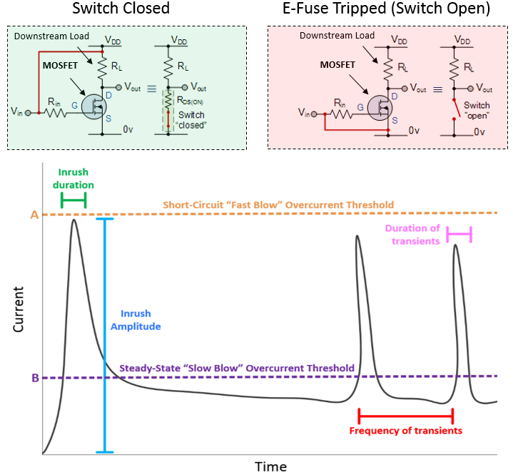
Current-Based Fault Protectionlink
Current-based fault protection measures a voltage drop across an external current sense resistor to determine current flow. If the current exceeds a configurable threshold, the eFuse opens the circuit. This type of protection is most often associated with discrete eFuses. An eFuse with current-based protection is relatively easy to match with the harness to make sure that there is adequate protection, but it is more difficult to design to prevent false trips because extensive characterization of the downstream loads is required.
 |
|---|
| Current-Based eFuse Fault Detection |
Discrete high side eFuses typically feature two levels of overcurrent protection:
- Short-circuit overcurrent protection: If current flowing through the eFuse exceeds the short-circuit overcurrent threshold, the eFuse will trip within 1 millisecond indicating a low-resistance "hard" short circuit has occurred.
- Steady state overcurrent protection: Some devices draw large bursts of current for short durations. To make sure these devices function properly, the eFuse allows current to exceed the steady-state overcurrent threshold, but only for a short period of time. However, the MOSFET will overheat if current of magnitude A flows through them for an extended period of time. Therefore, if the steady-state overcurrent threshold is exceeded for an extended period of time, the eFuse will trip.
Examples of devices that use these eFuses include:
- The main eFuses on the VCFRONT and VCBATT (iBooster, ESP, PCS, VCLEFT, VCRIGHT, EPAS)
- High-current H-bridges (seat motors, steering column motors, parking brake motors, window lift motors)
Temperature-Based Fault Protectionlink
Temperature-based fault protection is usually associated with integrated circuit style eFuses which features an internal thermistor (a resistor whose resistance is dependent on temperature). If the thermistor becomes too hot, the eFuse opens the circuit. These devices are typically not configurable. This type of fault protection is more tolerant to loads and conditions that are not fully characterized, but it is affected by ambient temperature.
On-Board Diagnostics (eFuse Self-Checks)link
Self-check steps for eFuses with no upstream turn-off path include:
- Measure voltage on output of eFuse (verify eFuse is off)
- Turn on eFuse
- Measure voltage on output of eFuse (verify eFuse is on)
- Turn off eFuse via fault injection.
- Measure voltage on output of eFuse (verify eFuse is off)
- Turn on eFuse
The purpose of these self-checks is to verify the eFuses can be turned off properly prior to shifting the vehicle into drive. For more information on how eFuses are used, refer to the HV Architecture - Power Electronics section.