Rear Trunklink
Last updated: October 20, 2023
This section gives an in-depth view of the operation of the powered liftgate.
Component Descriptionlink
Strutslink
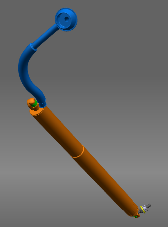
The Model S liftgate is equipped with struts to raise the liftgate. All new vehicles contain a powered liftgate, although some older vehicles contain a manual liftgate. The strut details are in the table below:
| Liftgate Actuation | Left Hand Strut | Right Hand Strut |
|---|---|---|
| Manual | Gas Strut (6006608-00-B) | Gas Strut (6009427-00-B) |
| Powered | Spring Strut (6006611-00-B) | Power Strut (6006610-00-B or 6006610-00-C*) |
The revision C power strut introduced in production after April 27, 2018 has more encoder counts, so if retrofitting it in place of a revision B, the gateway config must be updated, otherwise the liftgate will only open to ⅔ or usual height.
The power strut is an electrical actuator which is driven by the liftgate control module. The power strut also contains two hall sensors to track the position of the liftgate.
The power strut current draw is monitored by the liftgate control module. If there is an obstacle in the path of opening or closing, the current draw will increase beyond a threshold in the liftgate control module. This is one of the methods for liftgate obstacle detection.
Power Liftgate Strut Specslink
 |
|---|
There have been multiple versions of powered liftgate struts used on Model S.
Table 1. Powered Liftgate versions
| Motor Description | 6006610-00-B | 6006610-00-C (Start of Production: Oct. 26/2017) | |
|---|---|---|---|
| No Load | Speed (rpm) | 5000 | 6700 |
| Current Max (A) | 0.6 | 0.7 | |
| Stall | Torque Min (mNm) | 235 | 240 |
| Current Max (A) | 17.5 | 23 | |
| Cogging Torque | Dynamic Unpowered Motor Torque (mNm) | 5.0 | 4.0 |
| Max Allowable Speed (rpm) | 16000 | 26000 | |
| Diameter (mm) | 29 | 29 | |
| Length (mm) | 53 | 53 |
The motor mates with a planetary gearbox and internal screw to give the power strut extension. The powered liftgate strut also contains two hall sensors for position and velocity feedback to the power liftgate control module.
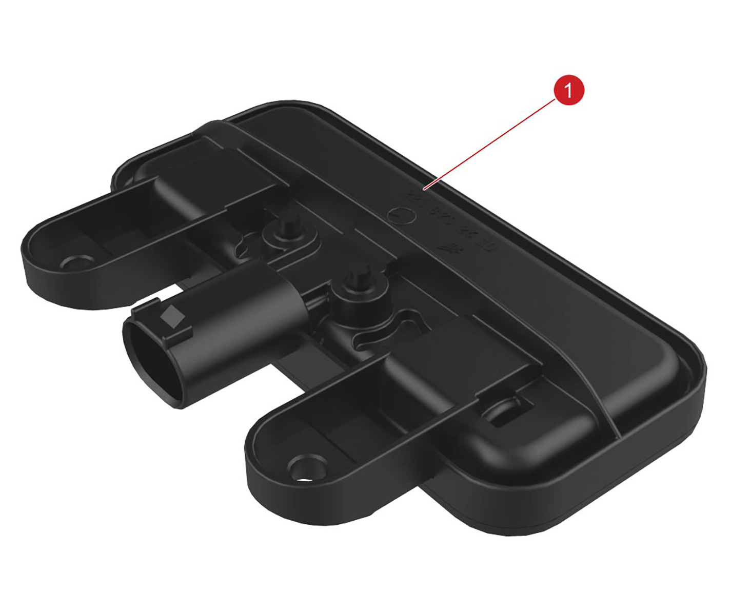
Liftgate Control Modulelink
 |
|---|
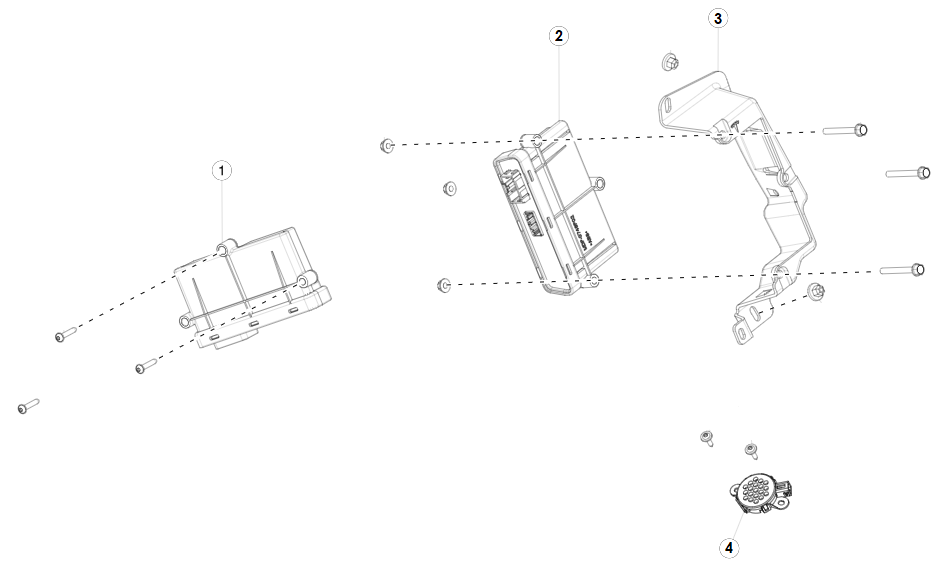
| 1. Electronic Park Brake Control Module 2. Liftgate Control Module 3. Liftgate Control Module Mount Bracket 4. Liftgate Chime |
The liftgate control module is made by a third party supplier and is located in the trunk on the right rear wheel arch. Removing the right-hand trunk liner provides access. The module has two harness connectors and is mounted to the bracket by three bolts. The control module operates the power strut movement and stores memory settings for the liftgate opening limit. It has the following power lift strut operations:
- Reverses liftgate motion when it receives input from the anti-pinch strip sensor.
- Reverses liftgate motion by monitoring current and detecting if an obstacle is present. If this occurs twice consecutively, the liftgate must be closed manually before power operation can resume.
- Controls operation of the cinching actuator.
Touchscreen Controllink
 |
|---|
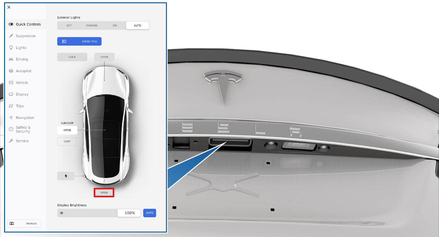
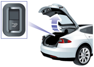
The trunk actuation can be accessed by opening the CONTROLS menu via the the bottom left hand side of the touchscreen. The trunk can be controlled by the OPEN button next to the rear trunk area as shown on the above screen.
Exterior Release Switchlink
 |
|---|
 |
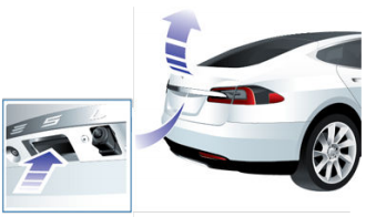
| 1. Exterior release switch |
| Liftgate Release Button |
The Exterior Release Switch is located directly above the license plate beneath a ledge on the liftgate. The exterior release switch is a simple contact switch with a direct connection to the body control module. The switch completes a path to ground when pressed.
The exterior release switch can be used to open the liftgate if the doors are unlocked.
Interior Release Switchlink
 |
|---|
The interior release switch is located on the left-hand liftgate trim panel. This switch connects to the body control module. It is only operational in vehicles with rear facing child seats and when the child protection lock is off.
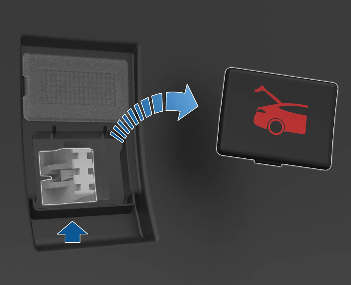
Interior Emergency Trunk Release Cablelink
 |
|---|
The interior emergency trunk release cable is located inside the rear trunk. This allows manual trunk actuation in the case of electrical/key failure, or in the case of people being stuck inside the trunk.
The component has a removable cover that is made out of glow in the dark material to allow location in dark environments. The cover needs to be removed by pulling outwards before accessing the cable.
The cable connects directly to the release latch. Upon pulling the cable, the trunk will need to be pushed up manually.
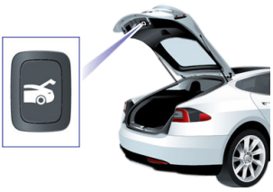
Liftgate Close Buttonlink
 |
|---|
The liftgate close button is located on the underside of the liftgate on models with the power strut actuator. The button connects to the body control module and tells the liftgate to close. It also is used to set the height of opening of the liftgate.
Anti-pinch Striptslink
The anti-pinch strip is located along the sides of the liftgate. The anti-pinch strip consists of two wires encased in the rubber seal. These two wires are connected to the liftgate control module. When an object is pinched, the two wires make contact with each other, and the closed circuit is detected by the liftgate control module.
Liftgate Latch/Strikerlink
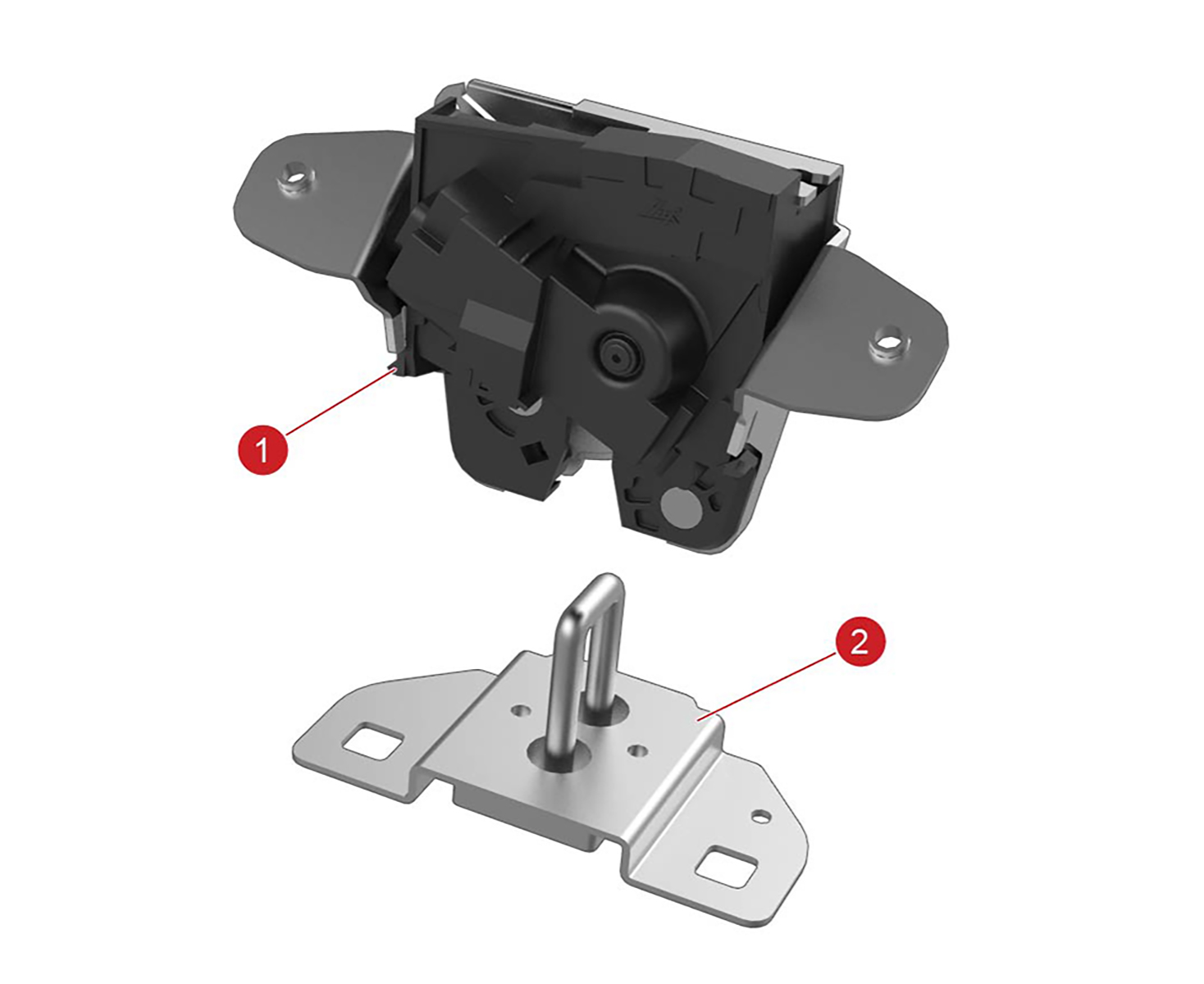 |
|---|
| 1. Liftgate latch 2. Liftgate striker |
The liftgate latch is on the underside of the liftgate. The striker can be adjusted for alignment. The latch contains a motor for releasing the hook, which is driven by the body control module.
The latch has a cinching feature for use with power liftgates. When the liftgate lowers and the striker engages the latch, the cinching actuator pulls a cable that is attached to a mechanical linkage on the latch. The linkage cinches the liftgate down to its fully closed position.
When the liftgate is open, an indicator icon displays on the instrument panel.
Note
The liftgate cannot be opened when Model S is moving. If an attempt is made to open the liftgate, a warning message appears on the instrument panel.
Liftgate Cinching Actuatorlink
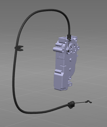 |
|---|
The liftgate cinching actuator inside the liftgate body. It is also driven by the liftgate control module for the models with the power liftgate.
The liftgate cinching actuator contains a cable housing attachment. The cable connects to the closing linkage on the latch, which cinches the latch shut. See the operation section for the description of the latch operation.
System Architecturelink
Note
Only connections relevant to the liftgate are shown. Please consult the Model S harness schematic for an up-to-date view of all connections between body controllers, sensors, and actuators.
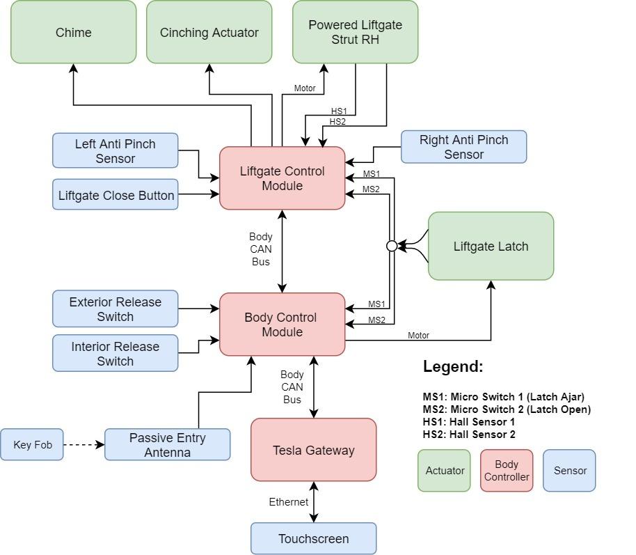 |
|---|
| Liftgate module interaction |
User Interactionlink
Opening the Rear Trunklink
Opening the rear trunk can be done in 5 different ways. Each method involves different components and communication protocol from the user input to the releasing of the latch.
- Press the trunk area on the key fob twice in quick succession.
- The key fob transmits the unlock request to the passive entry antenna.
- The passive entry antenna transmits the signal to the body control module.
- The body control module processes the unlock request and sends a CAN signal on the body CAN bus to the liftgate control module.
- The liftgate control module receives the CAN message and (if applicable) drives the power struts. The body control module actuates the liftgate latch.
- Using the touchscreen, press CONTROLS > TRUNK
- The touchscreen will process the unlock request, and the car computer will send that unlock request over Ethernet to the Tesla gateway.
- The Tesla gateway will process the signal, and then sen a CAN signal over the body CAN bus to the liftgate control module.
- The liftgate control module receives the CAN message and (if applicable) drives the power struts. The body control module actuates the liftgate latch.
- Unlock the Model S, then press the Exterior Release Switch under the
exterior handle.
- The exterior release switch is a simple contact switch. Upon pressing, the body control module detects a closed path to ground.
- The body control module processes the unlock request and sends a CAN signal on the body CAN bus to the liftgate control module.
- The liftgate control module receives the CAN message and (if applicable) drives the power struts. The body control module actuates the liftgate latch.
- Press the Interior Release Switch (vehicles with interior rear
facing child seats only).
- Pressing the interior release switch sends a signal to the body control module.
- The switch functionality is disabled if the child protection lock is left on. If the doors are locked, the body control module will unlock doors and await another push of the switch.
- The body control module processes the unlock request and sends a CAN signal on the body CAN bus to the liftgate control module.
- The liftgate control module receives the CAN message and (if applicable) drives the power struts. The body control module actuates the liftgate latch.
- Pull the Interior Emergency Trunk Release Cable.
- The cable connects directly to the trunk latch.
- Pulling the cable will manually release the liftgate latch. Push the liftgate manually up to open.
Closing the Trunklink
Closing of the Model S trunk can be done in the following way:
- Pull down on the liftgate and push firmly until it is fully closed. For vehicles without the power struts, this is the only way to close the liftgate.
- Double click the trunk button on the key.
- Using the touchscreen, press CONTROLS > TRUNK.
- Press the Liftgate Close Button.
Note
The power closing feature is temporarily disabled if the powered liftgate is open for more than an hour.
Adjusting Trunk Heightlink
If the vehicle is equipped with a power strut actuator, the opening height is adjustable to make it easy to reach.
- Open the liftgate, and then manually lower the trunk to the desired opening height.
- Press and hold the Liftgate Close Button for two seconds until a confirmation chime is heard.
- Confirm the setting changed to the desired height by closing the liftgate, then reopening it.
When the liftgate close button is held for two seconds, the liftgate control module stores the current position of the power struts in memory as the desired opening position.
Obstacle Detectionlink
Opening: If the liftgate is opening and detects an obstacle by an overcurrent on the strut, the chime will sound, and it will reverse and close.
Closing: If the liftgate senses an obstruction when closing by overcurrent on the power strut or by the pinch strip, it automatically opens and sounds two chimes. It will try to close again. If it cannot close the second time, powered operation is temporarily disabled. Close it manually to restore powered operation.
Component Operationlink
Liftgate Latchlink
Manual Liftgate Closinglink
Close the liftgate by pulling down on the liftgate and then firmly pushing it shut. Check that the liftgate is fully closed.
Powered Liftgate Closinglink
There are 4 ways to close the liftgate:
- Press the trunk area on the key fob twice quickly.
- Touch CONTROLS > TRUNK on the touchscreen.
- Cars with third row seats: press the Open/Close button located in the rear luggage compartment, on the LH trim panel.
- Press the Close button on the bottom face of the liftgate.
Note
On a Model S fitted with a power liftgate, a chime sounds when the liftgate starts to open or close.
Note
Pressing the button on the key, touching the icon on the touchscreen, or pressing the switch on the exterior handle stops the liftgate.
The latch consists of several plastic/metal linkages loaded by springs in a metal casing. The latch can be in an open, intermediate, or closed position. The animations below give a visualization of the different stages of the latch.
OPENlink
When the Model S is in Drive mode, the left side of the instrument panel shows a bird's eye view of the vehicle with the liftgate open and a warning message.
Note
The liftgate cannot be opened when Model S is moving. If an attempt is made to open the liftgate, a warning message appears on the instrument panel.
The hook is not in contact with the striker. The liftgate has not been lowered.
INTERMEDIATElink
 |
|---|
The striker (simulated by the red object in the video) makes contact with the latch linkage (black plastic with hook). This pushes the latch linkage, and moves the hook into an intermediate position. A secondary black linkage on the far left moves via a spring to lock the latch linkage in the intermediate position. This ensures that the latch linkage stays in this state after the pressure from the striker is released. The hook will loosely hold the striker in this position.
- If the liftgate is passive (not powered), this intermediate state is short lived, as the striker will continue to push the primary linkage until the latch enters the closed state.
- If the liftgate is powered, this position will release a micro-switch, causing the power struts to shut off, and the cinching actuator to engage the latch further.
CLOSEDlink
 |
|---|
Closing is achieved by pulling on the metal linkage at the bottom to move the latch linkage to the fully closed position. This process is known as cinching, and refers to the usual operation of the cinching actuator pulling on the metal linkage via a cable. Again note that in a passive liftgate, the metal linkage is not used. Cinching is achieved by the pressure of the striker on the latch linkage. The latch linkage and hook is held in the closed position by the secondary black linkage, which moves via a spring to lock the hook in place.
RELEASINGlink
 |
|---|
Releasing the latch is done by moving the secondary black linkage so that it releases the primary latch linkage back into the open position. Since the latch linkage is on a spring, it quickly snaps back into place. In the video, the actuation is done rotating the gear. In the actual liftgate, the gear is driven by a worm drive. Actuation of this white linkage pushes the secondary black linkage back into place.
Latch Indexinglink
 |
|---|
The latch is indexed by microswitches. The animation shows the secondary black linkage referred to above moving from the open to closed position. In the open position, both microswitches are pushed. In the intermediate position, only one microswitch is pushed. In the closed position, both micro-switches are extended. Thus, the latch can detect which position it is in, and feed back that information to the powered liftgate control module.
Powered Liftgate End Conditionslink
The liftgate can reach the end of travel by either reaching the top or the bottom.
When the liftgate reaches the bottom position, it will engage the intermediate position of the latch by pressing down the latch linkage. At this point, one of the micro-switches is released. This sends a signal back to the liftgate control module that the liftgate has reached the intermediate position. At this point, the power struts are shut off, and the cinching actuator is engaged to perform the cinching operation. When the metal linkage is pulled to move the latch to the closed position, the second microswitch is released, notifying the controller that the latch has completely closed. The cinching actuator is then released, and a spring pulls the metal linkage back to the original position.
When the liftgate is opening from the closed position, the motor drives the white gear via a worm drive to release the latch to the open position. When both microswitches are pushed, then the power struts are activated to open the gate. The liftgate strut will then operate until the end of travel is reached. The top position is configurable and stored in the liftgate control module. The two hall sensors track the position of the liftage and feed it back to the control module, allowing detection of when the liftgate reaches the top of travel.
Powered Liftgate Speed Controllink
The powered liftgate strut contains two hall sensors which feedback position to the powered liftgate control module.
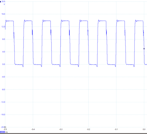
The controller is a velocity controller, meaning the objective is to keep the liftgate going at a constant velocity at all times. The liftgate strut is driven by pulse width modulation (PWM), which sends pulses at a specified duty cycle (percentage of time) and a frequency of (15 kHz). Picoscope traces of the PWM signal to the liftgate strut are shown below:
 |
|---|
| Motor+ as the Liftgate Opens |
Note
This picoscope trace shows the motor and the voltage. Motor+ to Motor-
The same signal is observed from Motor- when the liftgate is closed (strut is driven in the opposite direction).
The duty cycle of the above signal (percentage of time that it is on) is roughly 50%. The duty cycle changes throughout the travel of the liftgate in order to keep the speed of the liftgate constant.
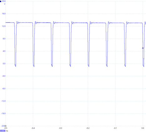 |
|---|
| Motor+ During Encounter With a Soft Obstacle as the Liftgate Opens |
If the velocity controller detects that the liftgate is moving slower that the target rate, it will increase the PWM duty cycle to the liftgate strut to increase the speed. Thus, the duty cycle is not constant during the entire path of the liftgate, since the opposing force is not constant throughout travel.
The above photo is a trace of the picoscope signal when the liftgate is being impeded upon opening by a hand. Notice that the PWM signal has a duty cycle of nearly 100%, as the liftgate control module is attempting to keep the liftgate at the constant speed through resistance.
When the PWM duty cycle reaches 100%, the motor will shut off, as the obstacle detection condition has been satisfied.