Non-Structural High Voltage Battery Deviceslink
Last updated: December 11, 2024
Overviewlink
High Voltage (HV) devices are HV components within the HV battery that supplement the primary functions of the HV battery. They are individual devices that gate, manage, convert, transform, measure, monitor and control energy moving through the HV battery module s.
The HV battery devices are located within an accessible section of the HV battery, referred to as the Ancillary Bay, because they are more likely to require servicing when compared to the modules within the platter.
Note
See Non-Structural High Voltage Battery Theory of Operation for more details on the platter and modules.
The HV devices group contains the following :
| HV Device | Purpose |
|---|---|
| Power Conversion System (PCS) |
|
| High Voltage Controller (HVC) | Includes the High Voltage Battery Management System (HVBMS) and High Voltage Processor (HVP) |
| Fast Charge Contactors | Connect the HV battery to the charge port for DC charging |
| Pack Contactors | Connect HV from modules to vehicle powertrain |
| HV Shunt | Measures HV current |
| HV Pyro-disconnect |
|
| Charge inlet connector | Connects PCS input to the charge port |
| HV fuses |
|
Power Conversion Systemlink
Specificationslink
The Power Conversion System (PCS) is a contained unit located within the Ancillary Bay which hosts all the controls and power electronics to convert electrical energy. The PCS converts Alternating Current (AC) to Direct Current (DC), steps up or down DC voltage (otherwise known as DC to DC or DCDC), and converts DC to AC (only for the second generation PCS).
PCS includes:
- A cooling plate with coolant inlet and outlet
- A top cover
- A PCBA with transformers
- Heat sinks
- Connectors
There are 2 generations of PCS. See table below for specification differences.
| Gen 2 | Gen 1 | |
|---|---|---|
| Size (mm) | 612 x 254 x 56 | 705 x 281 x 85 |
| Volume (liters) | 8.7 | 16.8 |
| Mass (kg) | 7.8 | 9.5 |
| Processor | TI Sitara | |
| Electrical conversions | Two planar magnetic devices | Single DCDC and 3-phase board converters |
| AC charging current capability | 3-phase: 16A/Phase 1-phase: 48A/Phase |
3-phase: 16A/Phase 1-phase: 48A/Phase |
| AC continuous power (kW) | 11 | 11 |
| Bi-directional charging | Yes | No |
| Always on DCDC | Yes | No |
| DC operating voltage (Volt) | 340 to 850 | 200 to 500 |
| Number of DCDCs | Two distinct DCDCs:
|
Single DCDC |
| DCDC continuous power (kW) | 3 | 2.5 |
| DCDC peak transient power (kW) | 6 | |
| DCDC capability (Amps) | 400 | 200 |
| DCDC output range (Volt) | 24-58 | 8-16 |
The HV battery of this platform is equipped with Power Conversion System Gen 1 (PCS1).
The PCS sits on a tray on top of the high voltage controller (HVC). The PCS is accessible once the front Ancillary Bay cover is removed.
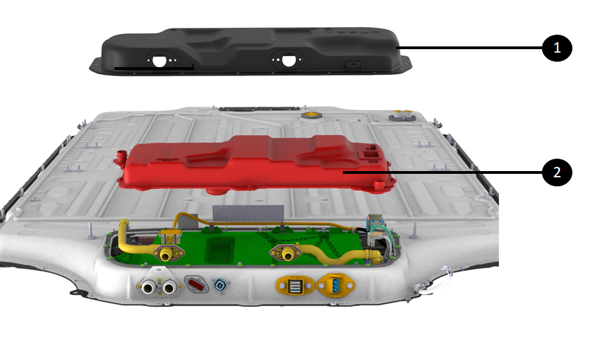 |
|---|
| 1. Front Ancillary Bay access cover 2. PCS directly underneath |
| Location of the PCS |
The PCS includes heat sinks that create improved thermal dissipation, which allows the HV battery PCS to reach higher peak power draws.
It also has a common AC filter to allow for both single-phase and three-phase variants.
Operationlink
The power conversion system performs the following operations:
- Converting AC to DC
- Converting DC to DC
Converting AC to DClink
When charging the HV battery on a Level 1 or 2 AC electric vehicle supply equipment (EVSE), the PCS transforms the wall power (120 VAC to 240 VAC) to a DC voltage corresponding to pack voltage (or slightly higher for the HV battery to charge). That voltage and current request comes from the HVC.
Note
See Non-Structural High Voltage Software Management Theory of Operation for more details.
During AC charging, PCS receives its charge request from:
- The HVC through Controller Area Network (CAN) or Etherloop
- A hardware enable line.
Both signals need to match in order for PCS to start converting power from AC to DC.
PCS is equipped with 4 AC terminals for line 1, line 2, line 3, and neutral. These lines are necessary to be able to AC charge from any AC power source in a wide voltage range.
PCS can support 3 phase AC input power. However, those 3 phases are shorted which only supports single phase AC charging.
Converting DC to DClink
The Power Conversion System Gen 1 (PCS1) features a single DCDC to convert high voltage from the HV battery to low voltage. During drive, charge, or while parked with HVAC active, the DCDC powers the low voltage bus which includes critical functions like power steering, braking, lights, and others. VCFRONT in 3Y and VCBATT in Model S and X (2021+) manage the power request to PCS2 for DCDC output power. The DCDC is also used to precharge the DC link bus when closing contactors. The PCS uses input LV power from the LV battery and steps it up to pack voltage. When voltage on DC Link and HV battery sides match, contactors are commanded to close.
The DCDC is able of outputting 2.5kW of continuous power with a maximum current of 200A.The DCDC output can range from 8V to 16V. The power line between the HV battery and DCDC is fused.
Serviceabilitylink
The PCS is replaceable in service as described in the repair manual. However, the internal components of the PCS are not serviceable. The entire unit gets replaced in service.
The replacement of the PCS does require removal of the HV battery as the Ancillary Bay cover is not accessible from the cabin. The PCS replacement procedure entails the following on Model S and X (2021+) vehicles:
- Removing the pyro-disconnect
- Removing of the HV battery (electrical isolation, removing rockers, aeroshield, bash plates, draining coolant and dropping HV battery, see details in the service manual )
- removing the Ancillary Bay cover,
- draining coolant from the PCS,
- Once the PCS connectors and fasteners are removed, the PCS should be handled with two vacuum suction cups to pull it out of the Ancillary Bay (shifting to the LH side to clear the battery enclosure lip).
There are no specific calibrations or configurations to perform after installation of the new unit. However, a software redeploy is necessary after replacement to have the new PCS software version match the version that is installed on the vehicle.
On the LV side, the PCS can convert up to 2.5kW of power between the DC link and LV output. The drawing below locates the PCS within the Ancillary Bay, but it is purposefully displayed outside of the Ancillary Bay for easier identification.
High Voltage Controllerlink
Specificationslink
The illustration below shows the HVC within the front Ancillary Bay. to access the HVC, it is necessary to remove the PCS and its supporting tray.
The Model S and X (2021+) HV battery HVC received further updates compared to the HVC used in Model 3 and Model Y at the time of launch.
General changes to the HVC applicable to all platforms:
- The side of the board was increased for a boost to 80W of the standby power supply
- This translated to a bump out in the area of the HV connector
- The bump affects the plastic housing and the hinge the board sits on
- The energy reserve power was increased (see Energy Reserve section)
- Reduced amount of potting for the LV connector to account for PCBA size increase
Changes specific to the revision of HVC installed in Model S and X (2021+) HV batteries:
- Higher hardware over current limit
- There is no Ancillary Bay high voltage interconnect loop (HVIL) lid, so there is a bypass resistor on the board
The Model S and X (2021+) HV battery uses HVC part number 1106394-x3-x. (1106394-x1-x is used for Model 3 / Model Y long range HV batteries, and 1106394-x2-x is used for Model 3 / Model Y standard range HV batteries).
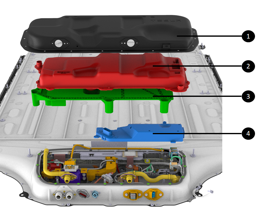 |
|---|
| 1. Front Ancillary Bay access cover 2. PCS 3. PCS tray 4. HVC right under the PCS tray |
| High voltage controller (HVC) |
Operationlink
The HVC is the brain of the energy and power distributed to the vehicle.
The HVC hosts a large PCBA which contains the main two processors : - The High Voltage Battery Management System (HVBMS) - The High Voltage Processor (HVP)
Both of these systems allow sensing, data processing, and controlling HV components. The HVBMS is more linked to the cells and the HVC to the HV components of the HV system. The drawing below shows the HVC within the ancillary bay.
High Voltage Battery Management System (HVBMS)link
The high voltage battery management system (HVBMS) manages cell data. It is the system that calculates data used for information display, driving limits, charging limits, and faults. The HVBMS receives high frequency high accuracy data from Application-Specific Integrated Circuits (ASICs) on the Battery Management Boards (BMBs). The HVBMS reads brick voltages and module temperatures via the BMB two-way communication link.
High Voltage Processor (HVP)link
The High Voltage Processor (HVP) controls the HV components, and the pyro disconnect. It is the system that will close and open contactors and contactors.
As the brain of the HV battery, the HVC controls all functions and HV devices via software.
Note
See Non-Structural High Voltage Software Management Theory of Operation for more details on the HVC software controls of the high voltage devices.
Serviceabilitylink
The HVC internals cannot be serviced. The HVC itself can be replaced .
Note
The HVC holds non-volatile data related to the platter and other components in the Ancillary Bays. Therefore, when replacing the device cluster some data from the old HVC has to be copied over to the new one.
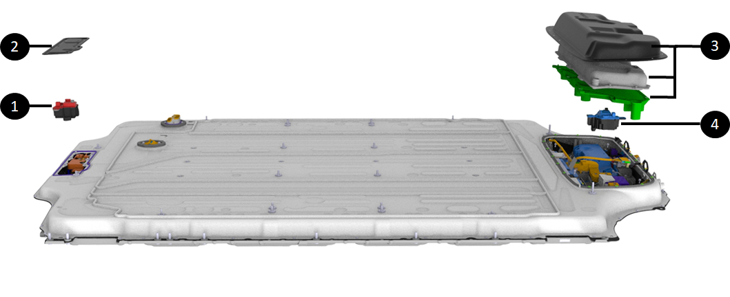
Pyro-disconnectlink
The pyro-disconnect is a standalone device able to interrupt the high voltage loop on the HV battery side of packs contactors.
Specificationslink
The pyro-disconnect is a busbar with a squib and pyro element. When fired, the squib breaks the busbar and opens the electrical connection.
The pyro-disconnect has an internal exhaust system that can dissipate the heat and particles generated by the arc when the HV connection is broken under heavy current. It is designed to be harmless when triggering in a person's hands.
The pyro-disconnect is located close to the HVC for optimized performance and reliability.
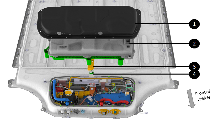
The pyro-disconnect is accessed via a cover that makes it serviceable without dropping the HV battery. It can be accessed directly from under the vehicle when the vehicle is on a lift.
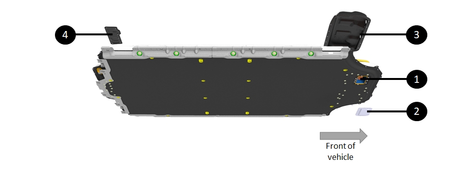 |
|---|
| 1. Location of pyro-disconnect in the HV battery, or pyro-disconnect cave 2. Pyro-disconnect access cover 3. Front Ancillary Bay access cover 4. Rear access panel cover |
| Location of pyro-disconnect |
Operationlink
The pyro-disconnect squib is triggered by the HVC via a dedicated wired connection. The HVC triggers the pyro-disconnect to interrupt the High Voltage loop for the following different conditions:
| Condition | Alert Log Signal | Description |
|---|---|---|
| Over current detected | PYRO_HANDLE_ OVER_CURRENT | There are two over-current detection mechanisms.
|
| Shunt MIA | PYRO_HANDLE _SHUNT_MIA | If the HVP is not receiving any current readings from the shunt, it will ask the HVC to trigger a graceful power off where discharge current will be ramped down, a message is displayed in the UI for the driver, and contactors will open 30 seconds after the graceful power off started. If that process failed, the HVP would fire the pyro after one minute. |
| Arc detected in contactor | PYRO_HANDLE_ PACK_POSITIVE_CTR_ARC PYRO_HANDLE_ PACK_NEGATIVE_CTR_ARC | The system has detected a significant voltage drop across a contactor when supposedly closed. |
| Impact detected | PYRO_HANDLE _ENS_CRASH | Impact signal is from the Restraint Control Module (RCM). The HVP is directly connected to the RCM. If that signal indicates an airbag deployment, the HVP will trigger the pyro-disconnect. The pyro-disconnect will have to be replaced after any collision or airbag deployment. The Emergency Notification Signal (ENS) is one wire from the RCM to the HVP. The ENS information is communicated by the frequency of the physical signal alternating between the high (6.6V) and low states (1.5V). When the RCM qualifies an impact, it transitions ENS PWM signal from 10Hz to 1kHz |
| Software over discharge current | PYRO_HANDLE_ OVER_DISCHARGE_CURRENT | The HVP will fire the pyro if the discharge current is above a certain threshold defined according to the config block which translates the type of HV battery connected to the HVC. That threshold is obviously below the hardware over-current. |
| Software over charge current | PYRO_HANDLE_OVER_ CHARGE_CURRENT | The HVP software will fire the pyro if the charge current is above a certain threshold defined according to the config block, which translates to the type of HV battery connected to the HVC. During charging, there is not passive over-current detection/protection. |
| Contactors need to be opened, but cannot | PYRO_HANDLE_ OPEN_IMMEDIATELY | The HVC software will fire the pyro if a condition requires the system to open contactors, but conditions are not met. Either the current is too high across contactors (contactors cannot open under high current), or contactors are welded, or there is no current value available, etc. Usually, this feature of firing the pyro when not suitable to open contactors is used after detecting an over temperature, a brick overvoltage, an undervoltage, or other conditions while current is too high to open contactors. |
Sequence of events for the pyro-disconnect to interrupt the HV loop:
- HVC triggers a current to excite the squib via connector (see item 6 below)
- The pyro element fires (see item 4)
- The busbar is pulverized (see item3),
- The arc inhibitor absorbs the arc generated by current interruption (see item 2):
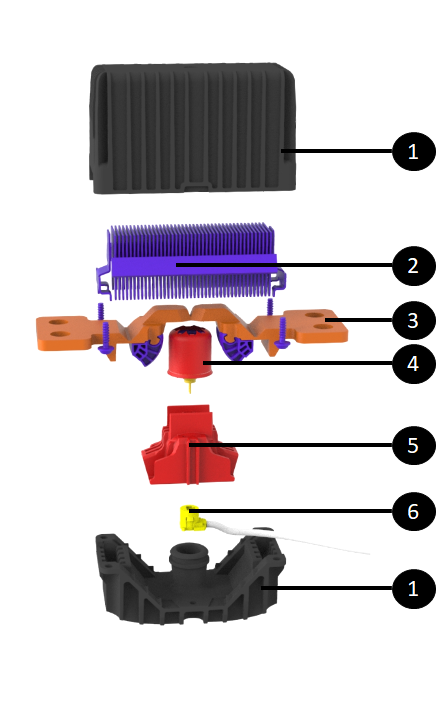 |
|---|
| 1. Pyro-disconnect housing 2. Arc inhibitor 3. Pyro-disconnect busbar 4. Squib / pyro element 5. Squib housing 6. Connector to HVP to trigger squib |
| Exploded View of HV Pyro-Disconnect |
Serviceabilitylink
Warning
There is always high voltage at the busbars connected to the pyro-disconnect (even with contactors open). Appropriate PPE is required for servicing, including eye protection in case of arcing or the pyro-disconnect firing during installation.
The pyro-disconnect cannot deploy if it is disconnected from the HVC, as the HVC supplies the current to trigger the squib. This means that the pyro-disconnects should always be removed before disconnecting it from the HVC or replacing the HVC.
The Model S and X (2021+) HV battery pyro-disconnect is bigger to allow for higher peak current. It is not interchangeable with pyro-disconnect from 3 and Y.
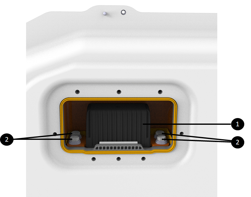 |
|---|
| 1. Pyro-disconnect 2. Four fasteners for pyro-disconnect to bus bars |
| HV pyro-disconnect |
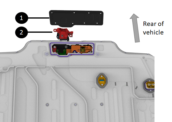
The pyro-disconnect is accessible from underneath the vehicle without dropping the HV battery. It is located at the front of the HV battery, right underneath the Ancillary Bay. There is an access panel with 8 fasteners and a seal.
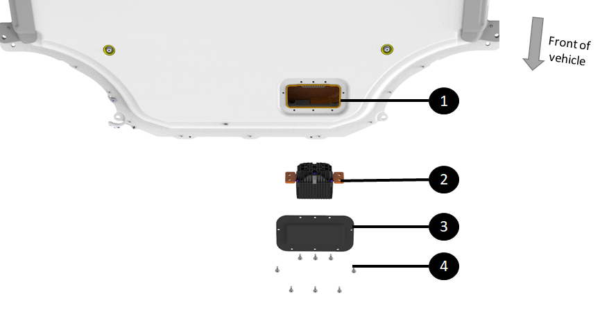 |
|---|
| 1. Cave in the HV battery for pyro-disconnect 2. Pyro-disconnect 3. Pyro-disconnect access cover 4. Cover fasteners |
| HV Pyro-Disconnect, Outside the HV Battery |
High Voltage Shuntlink
Specificationslink
The shunt is used by the HVC to measure current flowing in and out of the HV battery. The shunt is a copper busbar of a known precise resistance. The shunt does not have a microprocessor. On top of the shunt busbar is a small PCBA with passive electronic components to measure the voltage across the copper busbar and a connector for the harness to the HVC.
The shunt used in the Model S and X (2021+) HV battery is similar to the one used in the Model 3 / Model Y HV battery. It is just bigger to allow high peak and sustained currents.
 |
|---|
| 1. Front Ancillary Bay cover 2. Power conversion system (PCS) 3. Shunt isolator 4. Shunt |
| Shunt access |
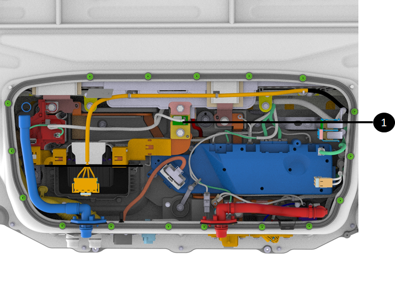 |
|---|
| 1. Shunt |
| Shunt location |
Operationlink
The shunt bar resistance, gain, and temperature coefficients are flashed onto the HVC during device cluster manufacturing line. Once the HVC knows the shunt bar resistance, it can determine the current flowing through the shunt from the measured pack voltage across the shunt.
Two wires connect the HVC to the shunt for the HVC to obtain the voltage across the shunt. Another pair of wires facilitates the passive hardware over-current feature described in the Pyro-disconnect section above.
Note
This pair of wires is also used as an auxiliary current sense. The HVC performs a sanity comparison of that current with the primary one to make sure that there is no hardware issue on either of those two current sense systems.
Two wires connect a small thermistor on the shunt bar to the HVC allowing the HVC to know the shunt bar temperature.
One last wire from the shunt to the HVC provides voltage input for the energy reserve in case the pyro was blown. When that occurs, the energy reserve is powered two cell-arrays, and one input is at the shunt.
Serviceabilitylink
The shunt is replaceable in service as described in the repair manual.
The procedure entails:
- Removal of the pyro disconnect
- Removal of the HV battery from the vehicle
- Removal of the front ancillary cover to gain access to the HV devices
- Removal of the PCS and its tray
- Removal of the shunt
Once the shunt is replaced, the HVC needs to be calibrated to the new shunt data. Refer to the repair manual for more details.
The shunt resistance being hard coded into the HVC, means that when either the HVC or the shunt is replaced in an Ancillary Bay, the shunt bar resistance has to be updated in the HVC.
Toolbox has a routine to perform this pairing.
HV Pack Contactorslink
The pack-contactors in the HV battery are the gate between the HV from modules and the rest of the vehicle.
Specificationslink
The pack-contactors are made of a single low resistance electrical contact point that moves along with a flexible busbar made of numerous thin layers of copper. The assembly connects to a movable rod that is in a magnet wrapped in a coil.
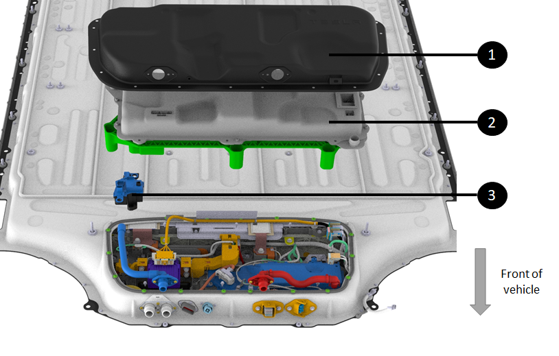
The location of the Model S and X (2021+) HV battery positive contactor is at the rear and the negative contactor is at the front of the HV battery. This positioning allows greater distance between the most negative and most positive points of the pack, to reduce the risk of high potential short circuits.
 |
|---|
| 1. Positive contactor in rear access panel 2. Rear access panel service cover 3. Front Ancillary Bay cover, power conversion system (PCS), and PCS tray need to be removed to access negative contactor 4. Negative contactor |
| Pack-contactors |
The negative contactor pulled out of the front of the Ancillary Bay for better visualization:
 |
|---|
| 1. Front Ancillary Bay cover 2. Power conversion system (PCS) 3. Negative contactor |
| Negative contactor |
The positive contactor pulled out of the rear access panel for better visualization:
 |
|---|
| 1. Front Ancillary Bay cover 2. Positive contactor |
| Positive contactor |
Operationlink
Current flowing through the coil creates a magnetic field that pushes the rod up. The pack-contactors have a massive coil which allows high force to close the contact, and the mass allows heat dissipation.
The pack-contactors are NOT designed to open under load. There is not enough spring force to pull the contact down when opening under load while arcing would try to bring the contact back together. Therefore, the system will not try to open contactors under high current if a fault occurs. The system will trigger the pyro-disconnect to first break the HV loop and then will open the HV battery contactors.
Serviceabilitylink
Warning
It should never be assumed contactors are fully opened when contactor power has been removed. Before working on a high voltage system, be sure to follow the Vehicle Electrical Isolation Procedure from the Service Manual to confirm with measurements that high voltage is not present.
Pack-contactors are both serviceable independently. Contrary to pre-2021 Model S and Model X, both contactors do not need to be replaced if one is replaced. Pack-contactor replacement is described in the repair manual. The procedure entails:
- Removal of the of the second row seat cushions
- Performing the vehicle HV disablement procedure
- Removal of the pyro disconnect
- Removal of the Ancillary Bay cover to gain access to the shunt
- Removal of the either pack-contactor
Fast Charge Contactorslink
Specificationslink
The fast charge contactors assembly is made of two contactors encapsulated in the same housing. The sense leads and contactor drive are included in a single connector at the top of the assembly between the two contactors.
Note
The fast charge contactors have a second redundant (auxiliary) switch to monitor the physical position of the contactor (open or closed).
When the fast charge contactor is in an "open" position, the switch should also be open and measure an open circuit across the terminals.
There have been cases where the contactors are open, but one of the contactor position monitor switches is stuck. This will still trigger fast charge contactor welded alerts.
The diagram below points to the pin-out of the fast charge contactor assembly.
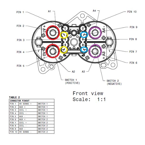 |
|---|
|
| Pin-out of the Fast Charge Contactor Assembly |
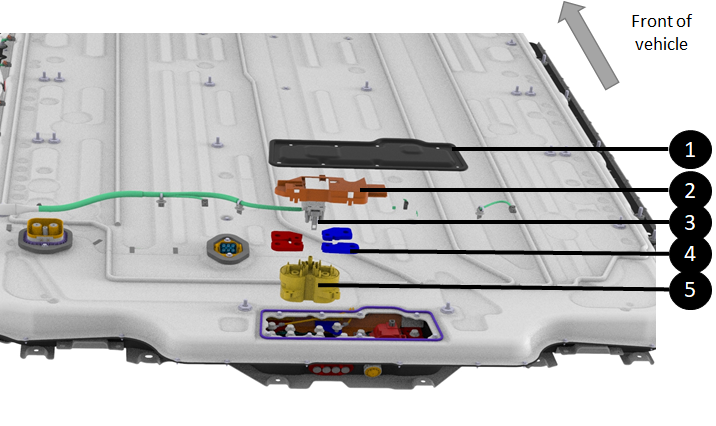 |
|---|
| 1. Rear access panel cover 2. Fast charge contactor assembly insulator 3. Fast charge contactor assembly connector (drive and sensing) 4. Bus bar to fast charge contactor assembly 5. Fast charge contactor assembly |
| Location of fast charge contactor assembly |
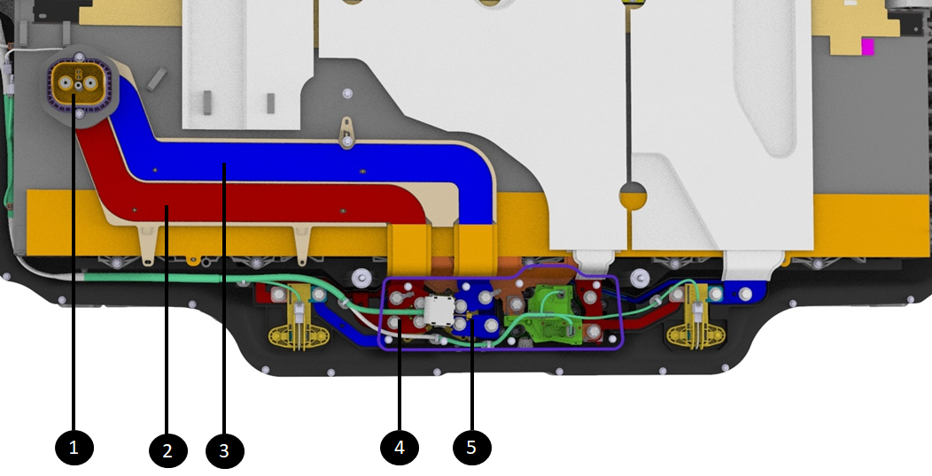 |
|---|
| 1. HV battery inlet charge port busbar connector 2. Positive fast charge busbar 3. Negative fast charge busbar 4. Positive contactor of fast charge contactor assembly connecting positive fast charge busbar to positive DC link 5. Negative contactor of fast charge contactor assembly connecting negative fast charge busbar to negative DC link |
| Fast charge contactor assembly to fast charge connector inlet |
Operationlink
The fast charge contactor assembly connects the DC charge port inlet to the pack. This allows DC charging when the charging station or electric vehicle supply equipment (EVSE) is directly providing DC power to the pack.
Serviceabilitylink
The fast charge contactor assembly is a unit. A single contactor cannot be replaced on its own, only the entire assembly gets replaced.
As seen above, the fast charge contactor assembly is located behind the rear HV battery access panel. The HV battery needs to be removed from the vehicle to replace the fast charge assembly.