Infotainmentlink
Last updated: October 20, 2023
Overviewlink
Infotainment is a general term used to describe how a customer accesses vehicle settings, information, entertainment, climate controls, and audio. It has since grown to encompass navigation, connectivity, voice recognition, and, to an extent, mobile app and mobile controls.The Intel-based infotainment board is replaced by an AMD-based system in October 2021.
Note
For the AMD-based infotainment system Theory of Operation, see the following documents:
A top-level view of the entire Infotainment system, as seen through the touch display, is shown in the table below. All these features run on the Infotainment and Connectivity Electronic Control Unit (ECU) (Infotainment ECU) but some external components are needed.
Table 1. Infotainment System Overview
| User Interface Element | Description | Related Hardware |
|---|---|---|
| Bluetooth (BT) | Displays information from mobile phone features such as calendar, calls, call history, contacts, and dial pad. Plays music from mobile phone. | Bluetooth antenna |
| Wi-Fi connectivity | Allows vehicle to be connected via Wi-Fi. | Wi-Fi antenna |
| Cellular connectivity | Gives the vehicle access to cellular networks (LTE). | Connectivity card with SIM card (eSIM) and LTE antenna. |
| Media player | Internet radio (TuneIn or Spotify), streaming (Slacker), phone media, USB input, and FM/AM radio stations based on region. | Tuner Module, FM antenna, amplifier, component for Bluetooth, and LTE. |
| Maps and navigation | Maps, routing, traffic information, and charging network provided by Tesla. | Driver Assistance System (DAS) electronic control unit (ECU) and LTE components. |
| Browser | Application used to access the internet on the center display. | LTE components. |
| Rear-view camera | Allows driver to see objects behind the vehicle in addition to using the rear view mirror. Rear-view access is routed through the DAS ECU (more information available in the DAS section of Theory of Operation). | Rear-view camera component and DAS ECU |
| Voice recognition | Processes spoken commands and interacts with the phone via BLE. Requires internet connection. | LTE component, steering wheel controls, and microphone. |
| Vehicle controls | All vehicle controls such as driving, displays, doors, lights, suspension, etc. | Car computer and vehicle controllers (front, left, right, security). |
| Settings | All vehicle settings such as profiles, DAS, security, language/units, etc. | -- |
| Charging | Charging information, current limitation, charge scheduling, and charge port control. | For more information on charging, refer to Charging section of the Theory of Ops. |
| Climate control | Seat and in cabin climate control. Front and rear defrost. | -- |
| Energy | Average consumption and projected vehicle range. | -- |
| Phone | Address book and in vehicle calling. | BT antenna |
| Toybox | Location of Tesla easter eggs and Telsa Arcade. | -- |
| Entertainment | Access to Theater Mode. | -- |
| Software update | Firmware release notes, starting / scheduling updates, update preferences. | -- |
| Tesla Mobile App | Method of communicating and controlling the vehicle from the customer's phone. | -- |
Updating Vehicle Firmwarelink
The Infotainment system is updated periodically by a process called a firmware update. During a firmware update, the Infotainment ECU, Autopilot computer, and on-board control modules are all updated if needed. This process is managed by a program called the ice-updater, or Updater, that lives on the Infotainment ECU.
Car Computerlink
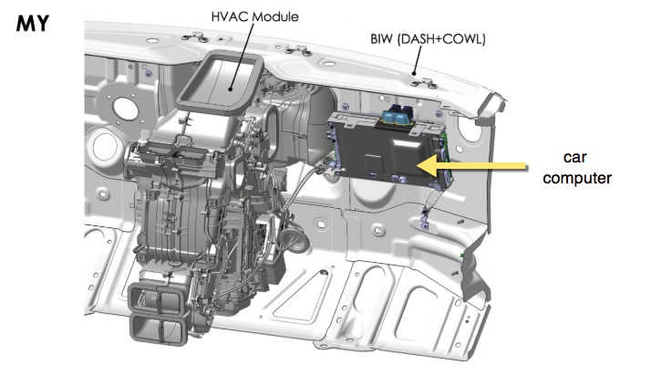
The core of the Infotainment system is the car computer. The car computer is made up of two ECUs: the Infotainment and Connectivity ECU (Infotainment ECU) and the Driver Assistance System ECU (DAS ECU). It is located behind the glove box on the passenger side of the vehicle, as seen in the figure below:
 |
|---|
| Car computer location |
Note
For information on the Driver Assistance System ECU, refer to the DAS section of the Theory of Operation.
The Infotainment ECU is the central interface for the Model Y Infotainment systems and contains the central processor, Ethernet switch, audio amplifiers, a connectivity card, and the Gateway.
The on-board diagnostic interface also runs on the Infotainment ECU.
The Infotainment ECU interfaces with the external modules listed below:
- Microphone array
- Premium audio module
- Radio/tuner module
- Touch display unit
- Front USB hubs
Infotainment and Connectivity ECUlink
Table 1. Noteworthy Infotainment ECU components
| Component | Short Name | Description |
|---|---|---|
| Main power | PWR | System power comes from front vehicle controller (VCFRONT). Once the power is supplied to the Infotainment ECU, it is filtered, switched, and stepped down as needed. Some of the board power rails are 12V0-AUDIO, 12V0-DISP, 3V3-BMP, and 5V0-SW. The Gateway senses some of these rails and broadcasts them over CAN. |
| Gateway | GTW | Refer to Gateway section below for more information. |
| Central processor | BMP | Central processor for the car computer. |
| A2B transceiver | A2B | The Automotive Audio Bus (A2B) is a high bandwidth digital audio bus which supports multiple serial communication protocols. |
| Audio amplifier 1 | AMP1 | Refer to Audio section below for more information. |
| Audio amplifier 2 | AMP2 | Refer to Audio section below for more information. |
| Wi-Fi | WLAN | Enables the Infotainment ECU’s Wi-Fi connectivity |
| Bluetooth | BT | Enables the Infotainment ECU’s Bluetooth connectivity. |
| USB front hub | UHUB | USB front hub contains a USB-C and a USB-A input. Refer to the External USB module section below for more information. |
| Embedded multi-media card | EMMC | Flash-based storage. |
| SPI flash | BOOT | Low-power flash memory that provides only serial access to the data. |
| Apple authentication | AAIC | Chip used to authenticate apple devices. |
| Display serializer | DISP | Serializes display data to the touchscreen. |
| Camera de-serliaizer | CAM | Turns the serialized data from the TI 913 serializer into displayable camera video. |
| PCIe to SGMII | I2101 | Interface between Intel Gordon Peak BMP and the Ethernet Switch, allowing the PCIe port to communicate with the Ethernet Switch. |
| Ethernet switch | ETH-SW | Used to connect components on the ethernet bus. Ports are locked to specific ECU connections for security reasons. |
| Connectivity | GSM | Enables the Infotainment ECU’s LTE connectivity. |
Gatewaylink
The Gateway is a critical component internal to the Car Computer. It contains a microprocessor which is responsible for:
-Communicating with each ECU in the vehicle as well as the Gateway diagnostic interface (gw-diag). - Handling CAN traffic for the chassis, vehicle and private networks. - Initiating the execution of UDS routines. - Authenticating access to the car computer via Ethernet for diagnostic purposes. - Maintaining a real-time clock which serves as the reference clock for the rest of the vehicle. - Interfacing with the SD card for log storage, which stores vehicle configuration.
The RING pin on the connectivity card (SMS wake request) is wired to the WAKE pin on the Gateway, meaning SMS wake requests will wake the Gateway, which will send wake signals over Ethernet to the other modules.
Car computer Power Sequencelink
Power is first directed to the Gateway from the front vehicle controller (VCFront). During the Gateway's application boot process, LED D10 flashes quickly. Once the Gateway's application is booted, LED D11 is illuminated and LED D10 flashes slowly. Power is then supplied to the BMP and the Gateway's microSD card. Once the BMP boots the Production Kernel Image, it then sends power to the display, indicated by illumination of LED D79. LEDs D13 and D79 are visible once the passenger footwell cover is removed. These LEDs can be used to quickly identify which state of the boot process the car computer is in. For instance, if LED D79 is not illuminated, the BMP is not running in the Production Linux Kernel, and could either be unresponsive or running in the Emergency Linux Kernel. Similarly if LED D13 is not illuminated, then the Gateway could be unresponsive or not running its application.
 |
|---|
Connectivity Cardlink
The connectivity card has two cellular coax antennae in a single connector that communicates with the 4G modem. Cell connectivity means the rest of the car can be put into asleep mode while the modem sits in a low-power paging mode and wakes all systems when it receives a page from the network (for example, wake or poke SMS). The card has a Wake input from the Intel Gordon Peak and a Ring output for waking the Gateway when an SMS is received. Audio is passed over I2S directly to the Infotainment ECU. All other data is passed over Ethernet.
Some key features:
- Supports eUICC soft SIM.
- Card is removable from the car computer.
- Does not hold the external SIM card.
The connectivity card in the Model Y is bolted down and requires removal of the car computer cover to access. Refer to the Service Manual for the specific replacement procedure.
Ethernet Switchlink
The Ethernet switch is an integral part of vehicle communication. It is a 6-port gigabyte switch that links several major components of the Infotainment system:
- Intel Gordon Peak BMP
- Gateway
- Radio/Tuner module
- Connectivity card
The Ethernet switch also provides a communication link with the DAS ECU and Diagnostic Port access. The switch is programmed with security measures to ensure that each client has an approved port and a list of approved hosts to communicate with. Each port is therefore programmed to a specific device, and they cannot be switched around for security purposes.
Infotainment External Component Descriptionslink
As mentioned previously, the infotainment and connectivity ECU also interfaces with the following components, some of which are external to the Car Computer:
- Touch display unit
- Antenna Module
- Microphone array
- Audio system, including premium/base audio module, radio/tuner module, amplifier.
- Connectivity System
- Front/rear USB hubs
- Inductive charger
Bluetooth and Wi-Fi Antennae Modulelink
Bluetooth and Wi-Fi Component Descriptionslink
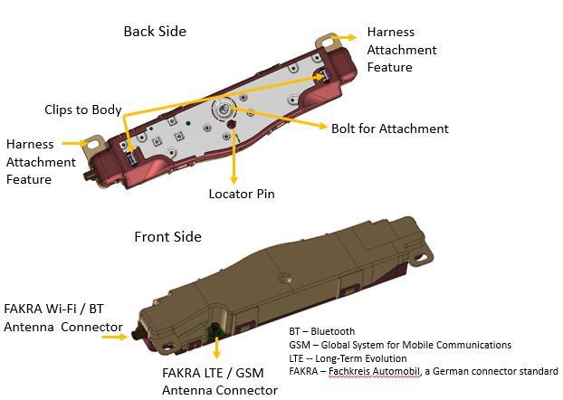
The Model Y introduces a new modular multiple-input, multiple-output (MIMO) antenna design for connectivity. The Antenna module contains two antennas:
- One multipurpose for Bluetooth or 2.4GHz Wi-Fi/5GHz Wi-Fi
- One specifically for LTE.
The Model Y uses two antenna modules located along the A pillar on the left and right side to support LTE diversity, Wi-Fi 5GHz diversity, 2.4GHz Wi-Fi, and Bluetooth, for a total of four antennas per vehicle:
- One Bluetooth/5GHz Wi-Fi
- One 2.⅘GHz Wi-Fi
- Two LTE
 |
|---|
| Multiple-input, multiple out-put (MIMO) antenna module |
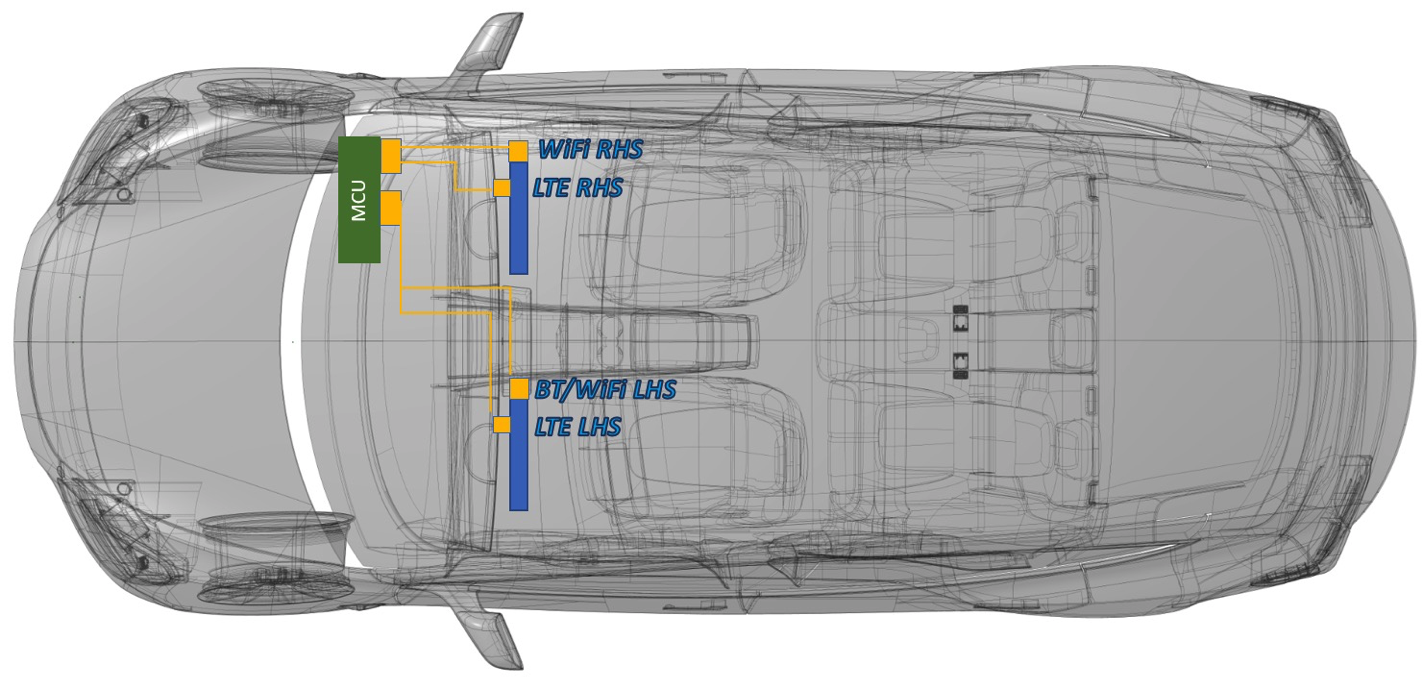
The location of the two modules is same for both left-hand drive and right-hand drive configurations, as shown in image below. The left-side module includes one LTE antenna and one Bluetooth/5GHz Wi-Fi antenna. The right-side module includes one LTE antenna and one 2.4GHz/5GHz Wi-Fi antenna. The harness is designed so that physical cable length prohibits incorrect connections from the Infotainment ECU to the Antennae to be made.
 |
|---|
| Antenna module left and right side locations |
For right-hand drive versions of the vehicle, the two antenna modules will stay in the same location. The car computer will change to the left side of vehicle, and harness will change to support this configuration.
Audio Systemlink
Base Audiolink
On-board base audio is driven by two DAC amplifier (4x40W output power). The base audio configuration has nine speakers:
- Four on the doors, one each.
- Four on the Instrument Panel (left, center, center tweeter, and right).
- One pedestrian warning.
Base Internal Audio Module
| Qty | Image | Size | Type | Location | Amplifier | Power |
|---|---|---|---|---|---|---|
| 1 | Center Channel | 100 mm | High Mid-range | Instrument panel | Base | 27w / 3Ω |
| 2 | Left & Right | 25 mm | Tweeter | Mid A-Pillar | Base | 20w / 4Ω |
| 2 | Left & Right | 100 mm | High Mid-range | Instrument panel | Base | 27w / 3Ω |
| 2 | Left & Right | 200 mm | Woofer | Front Door | Base | 20w / 4Ω |
| 2 | Left & Right | 100 mm | High Mid-range | Rear Door | Base | 27w / 3Ω |
Premium Audiolink
The premium audio module is external to the car computer. It has an A2B chip (slave) for communication. Since the premium audio package has seven additional speakers, this module contains two audio drivers at two different power output levels:
- DAC Amplifier (4x40W output power)
- Connected speakers are located at the left and right rear doors, as well as the left and right parcel shelf.
- DAC Amplifier (4x80W output power)
- Connected speakers are the left and right front door woofers and the sub-woofer in the trunk.
| Qty | Image | Size | Type | Location | Amplifier | Power |
|---|---|---|---|---|---|---|
| 1 | Center Channel | 100 mm & 25 mm | High Mid & Tweet | Instrument panel | Base | 27w / 3Ω |
| 2 | Left & Right | 100 mm | High Mid-range | Instrument panel | Base | 27w / 3Ω |
| 2 | Left & Right | 100 mm | High Mid-range | Rear parcel shelf | Premium | 27w / 3Ω |
| 2 | Left & Right | 60 mm | High Mid-range | Upper A-Pillar | Base | 60w / 4Ω |
| 2 | Left & Right | 100 mm | High Mid-range | Rear door | Premium | 27w / 3Ω |
| 2 | Left & Right | 200 mm | Woofer | Front door | Premium | 80w / 4Ω |
| 1 | LFE Channel | 200 mm | Sub-woofer | Rear quarter | Premium | 2x 80w / 4Ω |
Radio Tuner Module, FM Antenna, and Amplifierslink
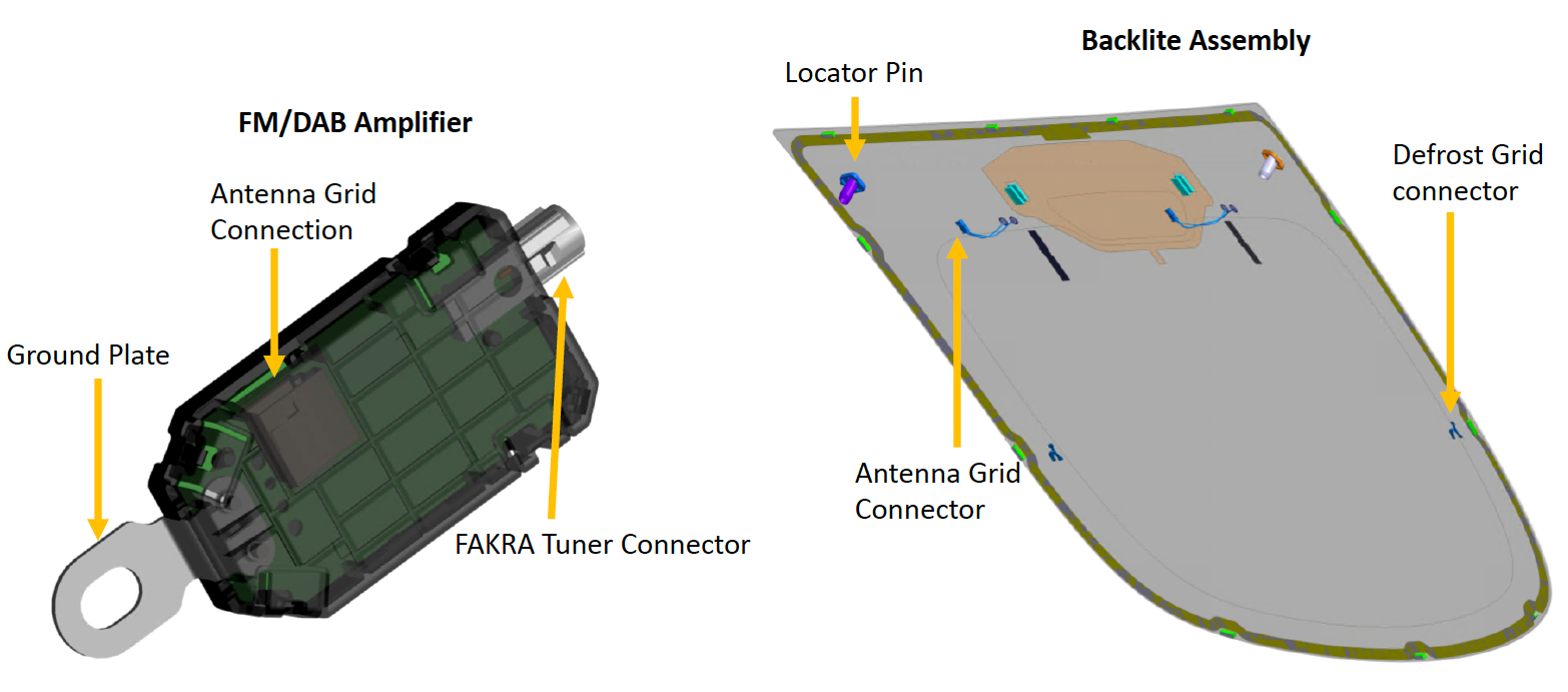
The Model Y uses two FM amplifiers secured to the top left and right of the liftgate by the amplifier’s ground plate. A single wire FAKRA connection connects the amplifier to the radio tuner. The amplifier is connected to the antenna grid on the backlite assembly via a two-wire copper wire connection which is soldered to the antenna grid.
For markets with DAB radio, the Model Y will consist of two FM/DAB Antenna Amplifiers. For North America (North America) and other markets, the Model Y will consist of two FM Only Antenna Amplifiers. Using FM / DAB Amplifiers for North America or APAC regions, or using FM amplifier for DAB regions, will result in self-test failure, and the tuner shows issues related to Antenna connection. In the first case, the tuner will report “Short to GND” and for the latter case, the tuner will report “Open”. The UI tab in the Engineering menu carries the tuner's reported Antenna values in the radio section.
 |
|---|
| Location of the FM/DAB amplifier |
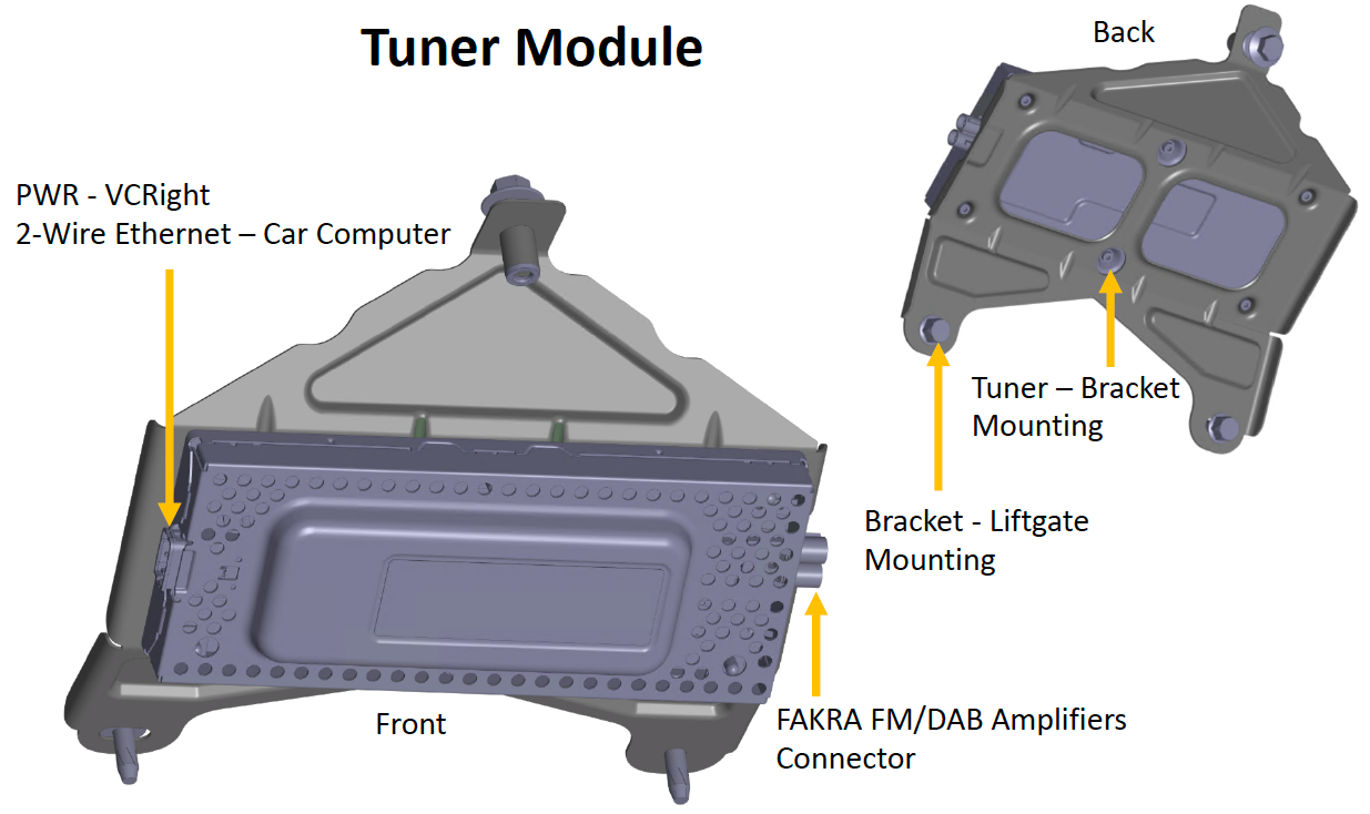
The tuner module is a carryover from the Model S and Model X with an updated mechanical design, which is mounted to the liftgate. Power is provided to the tuner module via the VCRIGHT. Communication to the car computer is made over a 2-wire ethernet connection housed in the same connector. The tuner module is connected to the FM/DAB amplifiers via a double FAKRA connector which splits in the harness for connections to each FM amplifier.
 |
|---|
| Location of the radio tuner module |
 |
|---|
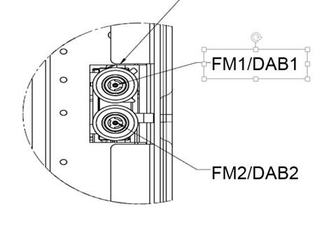
| The double FAKRA connector with individual signals |
Serviceabilitylink
The UI tab in the Radio Engineering page carries some data values for finding tuner related issues. If the tuner reports “Open” for antenna connections, then one of the three possibilities is happening:
-The double FAKRA connector is not connected at the tuner. - The FAKRA connector is not connected at the antenna amplifier. - The antenna grid connection is not connected at the antenna amplifier
If Tuner reports “Short to GND” for antenna connections, then one of the three possibilities is happening: - The wrong antenna amplifiers were used. - For example, if the FM/DAB amplifiers were installed in North America or APAC region vehicles. - The coax cable is shorted. - Check for a short end to end from tuner to amplifiers. With the coax cable disconnected on both ends tuner and the amplifier, center pin to shield should be open for the coax cables. - The antenna amplifier or tuner is damaged.
Problems seen by the customer if one of the antenna is connected and other not:
Table 1. Customer impact North America / APAC Region
| FM / DAB1 | FM / DAB2 | Functional Issues | Customer Impact |
|---|---|---|---|
| Open | Open | FM station list is unavailable and FM is not functioning. | Severe |
| Connected | Open | FM is performing, but with quality degradation. | Quality degradation is high |
| Open | Connected | FM station list is unavailable, but FM is partially performing. | Quality degradation is high |
| Short | Short | FM is performing, but with quality degradation. | Quality degradation is high |
Table 2. Customer impact DAB / EMEA Region
| FM / DAB1 | FM / DAB2 | Functional Issues | Customer Impact |
|---|---|---|---|
| Open | Open | FM and DAB station lists are unavailable. | Severe |
| Connected | Open | FM is performing, but DAB is not. | Quality degradation is high |
| Open | Connected | DAB is performing, but FM is not. | Quality degradation is high |
| Short | Short | FM and DAB are both partially working. | Quality degradation is high |
Touchscreenlink
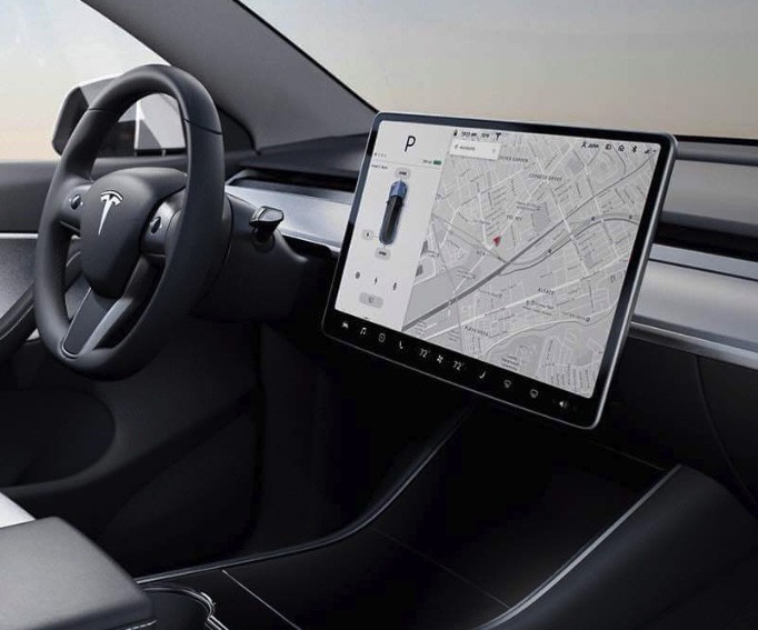
The integrated touchscreen (15" 1920x1200 display) handles all the processing for the touch controller and display locally. The touchscreen and its firmware are made a by a third-party supplier. This is the only user interface in the vehicle aside from the steering wheel buttons, so it provides essential driver information such as vehicle speed and gear. It also displays information related to cabin HVAC function, in-vehicle entertainment, maps and navigation, etc.
The touchscreen is external to the car computer, and can be removed without accessing the car computer. It has a single 6-conductor HSD connector, 12V supply.
 |
|---|
| Touchscreen in vehicle |
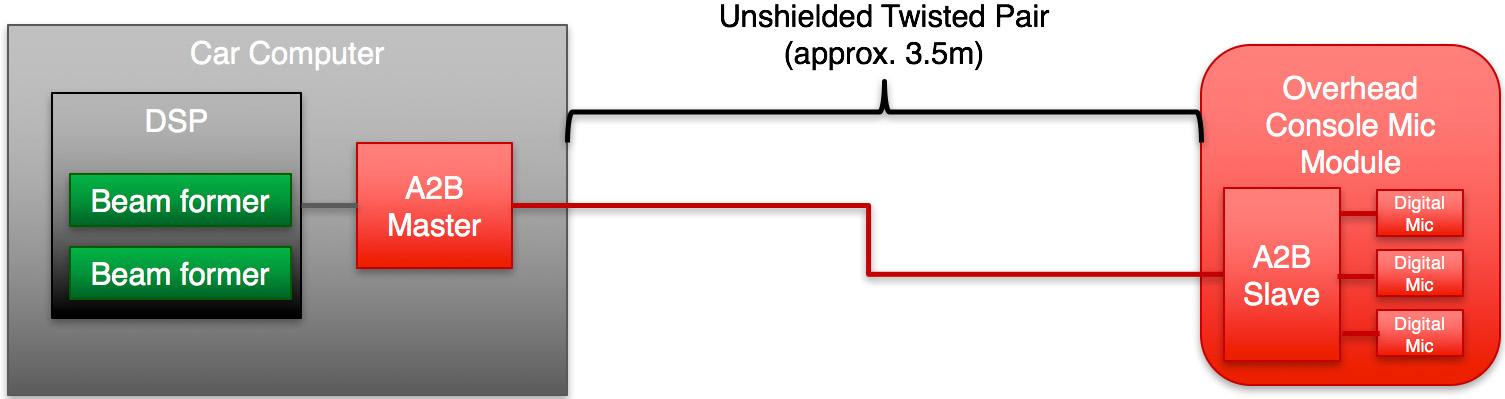
Microphone Modulelink
The microphone module has three digital microphones and one A2B (Automotive Audio Bus) chip (slave). The microphone module is connected to the master controller and the audio module that is internal to the car computer, making it an essential part of audio communication. The module is installed in the headliner near the rear-view mirror. The module sends digital audio data over time-division multiplexing (TDM) to the car computer. This is a twisted pair. Phone call data is sent on to the Bluetooth module and voice recognition is processed on the car computer.
 |
|---|
| Unshielded Twisted Pair |
External USB Modulelink
The Model Y comes with two USB modules.
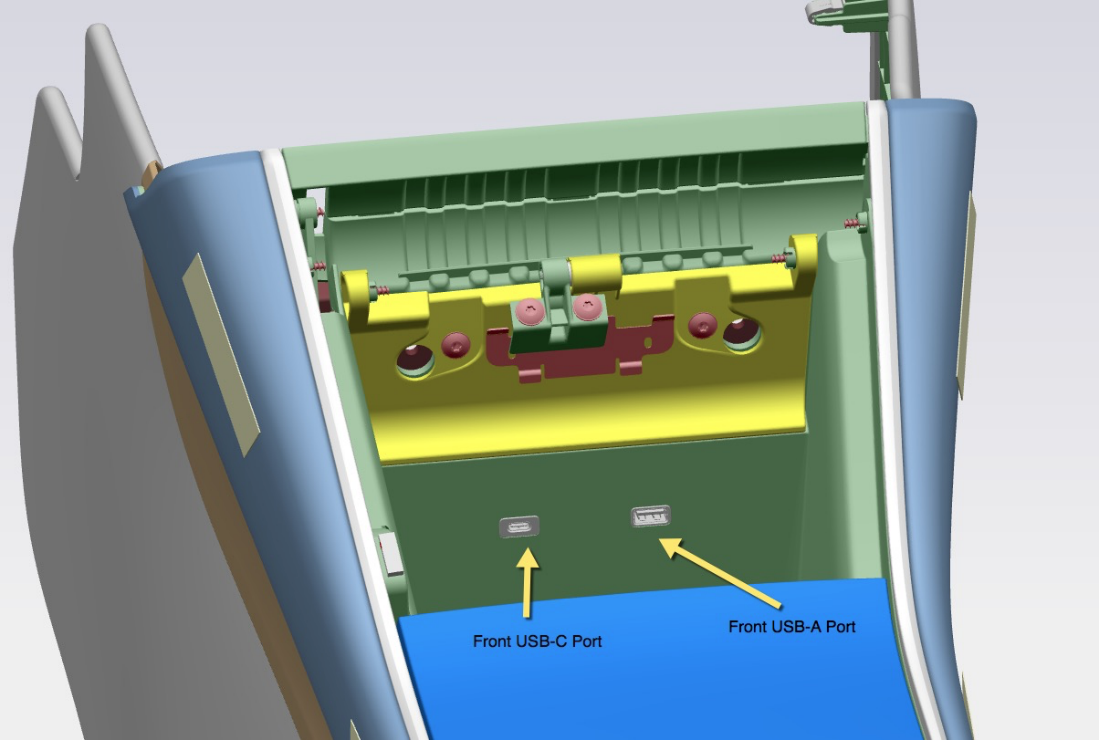
The front USB module is in the front of the center console and includes one USB-C and one USB-A port. Both front USB ports support power and data transfer. The USB-C port and the USB-A port are capable of charging at up to 27 watts and 12 watts, respectively. Both USB ports are USB 2.0, and offer maximum transmission rates of 480 Megabits per second (Mbps) each.
 |
|---|
| Location of the front USB-A and USB-C inputs |
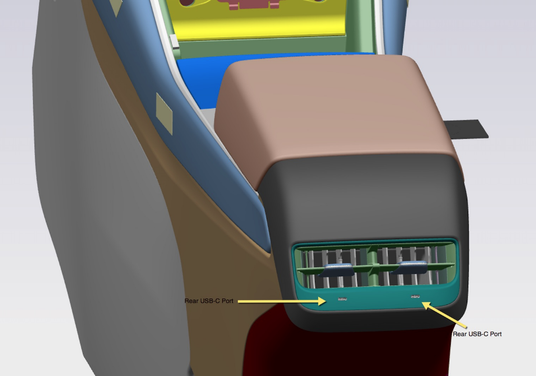
The rear USB module is at the back of the center console, under the rear cabin vent. It includes two (2) USB-C ports, each of up to 27 watts. The rear USB ports can only be used for charging.
 |
|---|
| Location of the rear USB-C inputs |
While the format-restrictions in place, the impact is restricted to the USB device itself when using it for media or Sentry Mode data. The front and rear ports are powered by 4-pin battery connectors, which provide 12V input and ground. Additionally, the front ports are connected to a fused, regulated USB-mini port on the Infotainment ECU for media purposes.
Inductive Charginglink
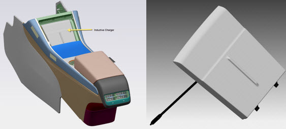
The Model Y comes with an inductive charger that sits in the front of the center console.
The inductive charger is powered through the USB-C port in the front USB hub. The connection to the car computer allows the charger to communicate with the car computer to indicate if and when a phone is charging. All phones capable of wireless charging (Qi Certified) can be charged using this wireless charger. The charging platform is capable of charging one phone on either side at a time, or two phones at the same time.
The wireless charger provides up to 15 watts.
 |
|---|
| Location of the induction charging unit |
Autopilot Hardware 3.1link
Autopilot hardware 3.1 (HW 3.1) supports gigabit ethernet between the DAS ECU and the car computer. HW3.1 also allows the car computer to debug content stored on a separate debug board instead of in the car computer itself.
For more information on the DAS-side of HW 3.1, please refer to the Driver Assistance section of the Theory of Operation.
UI Vocabularylink
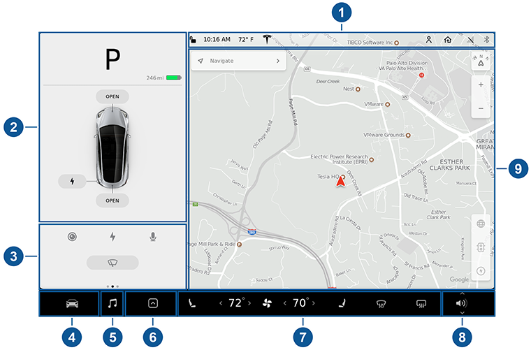 |
|---|
| Diagram of the center display UI |
|
Infotainment Glossarylink
| Acronym | Definition |
|---|---|
| A2B | Automotive Audio Bus. Used for the audio system. |
| BMP | Intel BGA (ball-grid array) Module Package, the system on a chip that runs the infotainment system. |
| BT | Bluetooth |
| GTW | Gateway |
| PCI | Peripheral Component Interconnect. A communication bus. |
| TDM | Time Division Multiplexd format. It is used with A2B audio. |