Steeringlink
Last updated: May 11, 2024
Overviewlink
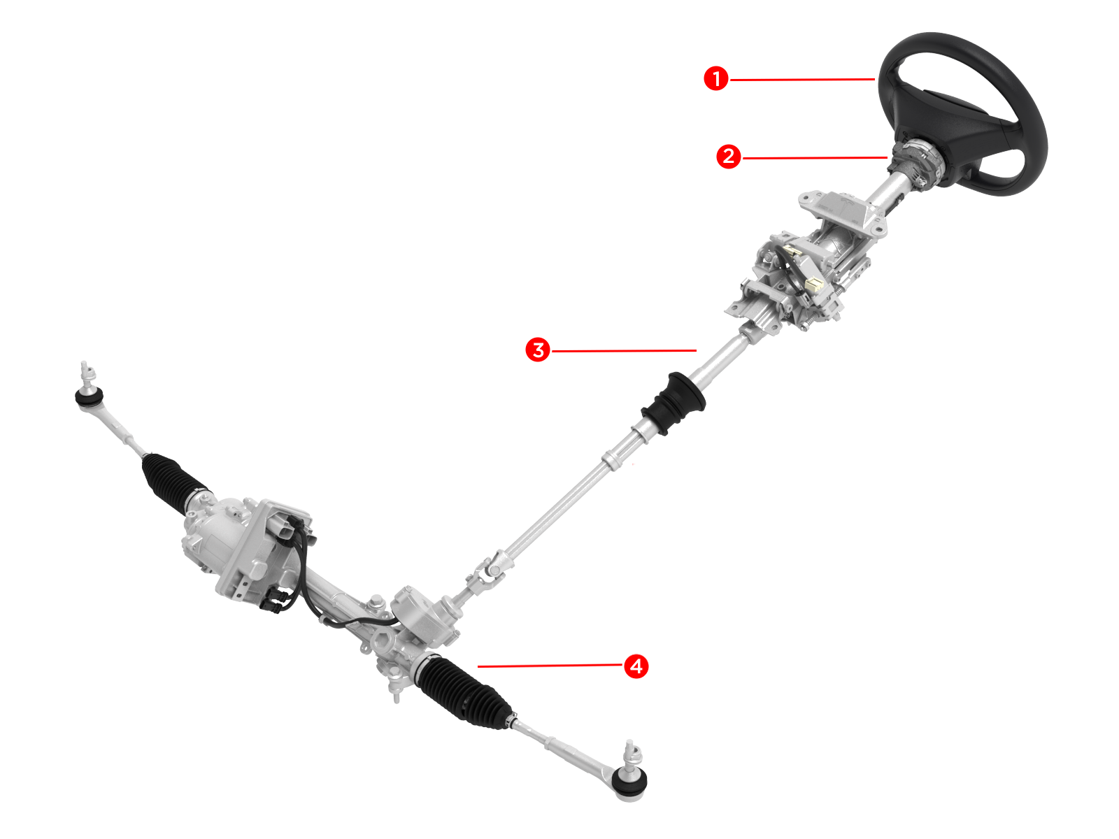
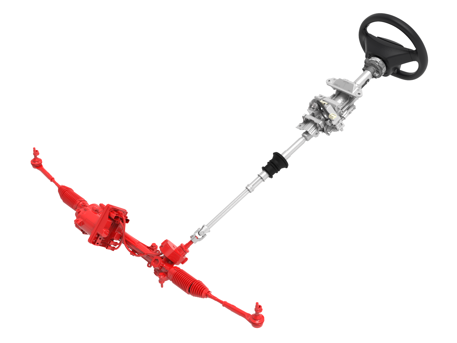
The system comprises a steering wheel connected to the electrically assisted power steering (EPAS) rack through the steering column and intermediate shaft. The steering column is mounted to the vehicle dashboard cross-car beam. The column is adjustable, which allows the steering wheel to be adjusted up and down and away from and towards the driver. The rack is bolted to the front subframe. Through tie rods, the rack connects to the steering knuckles, which hold the hubs, brakes, and road wheels. The steering rack is produced by Mando.
Electric Power Assisted Steering (EPAS) is a system that provides steering assistance for turning the front wheels on the vehicle. This system primarily uses torque input from the driver to determine how much assist the electric motor should provide. Other inputs include the selected steering feel mode, absolute steering angle from the column and vehicle speed.
In the event of a malfunction of the EPAS, the vehicle can still be steered through the mechanical connection between the steering wheel and the wheels. It will require greater effort than normal to turn the steering wheel in this situation because there is no assist.
 |
|---|
|
| Component Location, Overview |
Componentslink
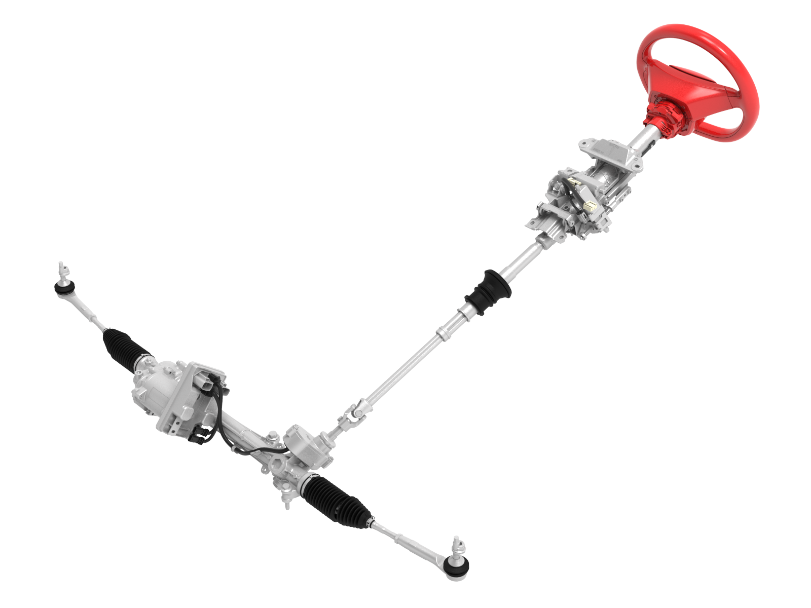
Steering System Overviewlink
Steering Wheellink
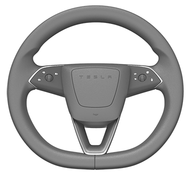
The steering wheel is located in front of the driver and is mounted to the steering column. It is the interface between the driver and the steering system of the vehicle. The steering wheel itself is a passive component designed to give the driver an ergonomic way of applying a steering input to the vehicle. The steering wheel is home to the Steering Wheel Controls (SWC) with captive buttons and scroll wheels which the driver can use to control multiple things (e.g. drive controls, infotainment controls) without having to let go of the steering wheel. The SWCs communicate via local interconnect network (LIN)-Bus with the left vehicle controller (VCLEFT). The steering wheel is also a bracket for the driver airbag. The steering wheel is a three-spoke yoke design. It is manufactured from molded rubber with a leather-trimmed rim. It is secured to the steering column using indexed splines and a countersunk hex drive screw. The indexed splines make it so there is only one position to fit the steering wheel relative to the column.
 |
 |
|---|---|
| Steering Wheel |
Steering Column Control Modulelink
The Steering Column Control Module (SCCM) is located just behind the steering wheel on the steering column. It is pushed onto the steering column and has a clip that snaps into a square hole in the column. A band clamp securely tightens the SCCM onto the column (screw torque 2-3 Nm). The SCCM features a Steering Angle Sensor (SAS) and has a clockspring to pass through the airbag connections and LIN communication to the Steering Wheel Controls (SWC). Communication between the SCCM and other controllers is via the vehicle controller area network (CAN). The SCCM is powered by VCLEFT.
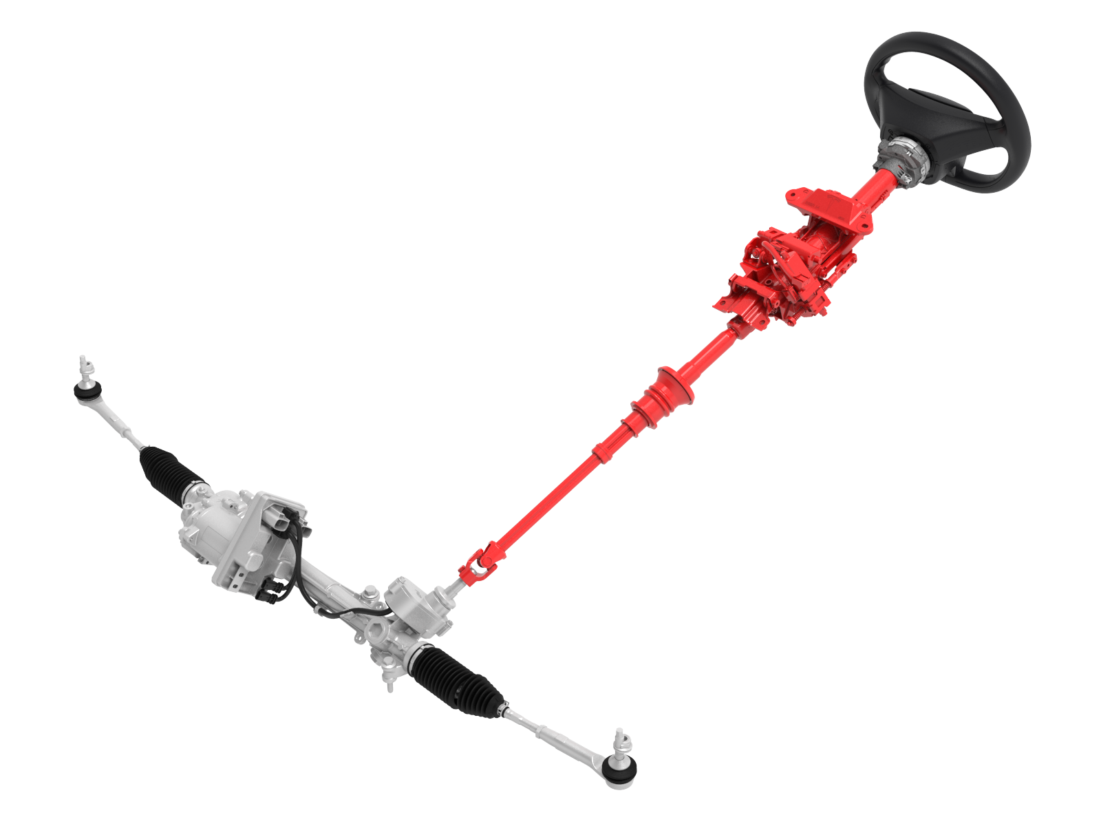
Steering Columnlink
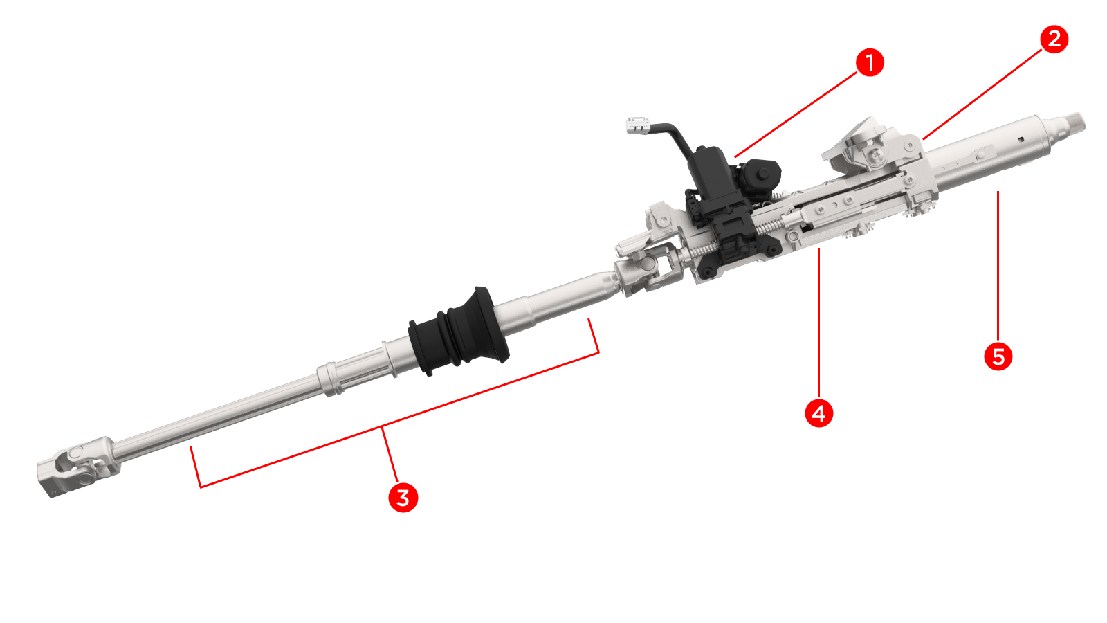
The steering column assembly comprises an aluminum base plate, a sliding carrier, pivot brackets, a collapsible shaft assembly, and an intermediate shaft. The sliding carrier is connected to the base plate. The upper column mounting pass through the column base plate and are secured into weld bolts by 4 nuts in the vehicle dashboard cross-car beam.
 |
|---|
| Steering Column Assembly |
The steering column supports the steering wheel and is adjustable for reach and height by the driver to allow for the most comfortable driving position. The adjustment is controlled by VCLEFT. Adjustment can be done manually by selecting the steering wheel adjustment menu on the touchscreen, then using the scroll wheels on the steering wheel to adjust. Two automatic adjustment features can be turned on as well. Based on driver profile settings, the steering wheel position will adjust to the current driver. If selected with easy entry, the steering wheel will automatically move to a pre-set position when the driver leaves the vehicle, and it will come back to the driver's set position when seated. The pre-set easy entry position gives the driver more room to enter and exit the vehicle. Two electric motors turn plastic drive nuts that are attached to drive screws, which in turn are connected to the upper pivot bracket and shaft assembly.
 |
|---|
|
| Steering Column Components |
Intermediate Shaftlink
The intermediate shaft is located between the steering column and the steering rack. It mechanically connects the two. It comprises a steel upper section and a lower section which both have a universal joint. The intermediate shaft is a two-piece part which can slide in and out but can still transfer torque by the use of splines or profile sleeve (four leaf TKP style). It is not separately serviceable and comes with the steering column.
Electric Power Assisted Steering Steering Racklink
The steering rack is mounted to the front subframe between the front wheels in front of the drive unit. It features Tesla 3rd generation Electric Power Assisted Steering (EPAS3). This system reduces the effort needed by the driver to turn the steering wheel. It allows for full self-steering.
 |
|---|
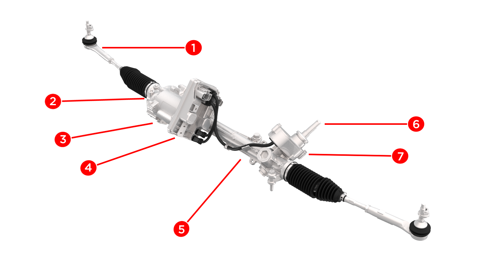
| Steering Rack Assembly |
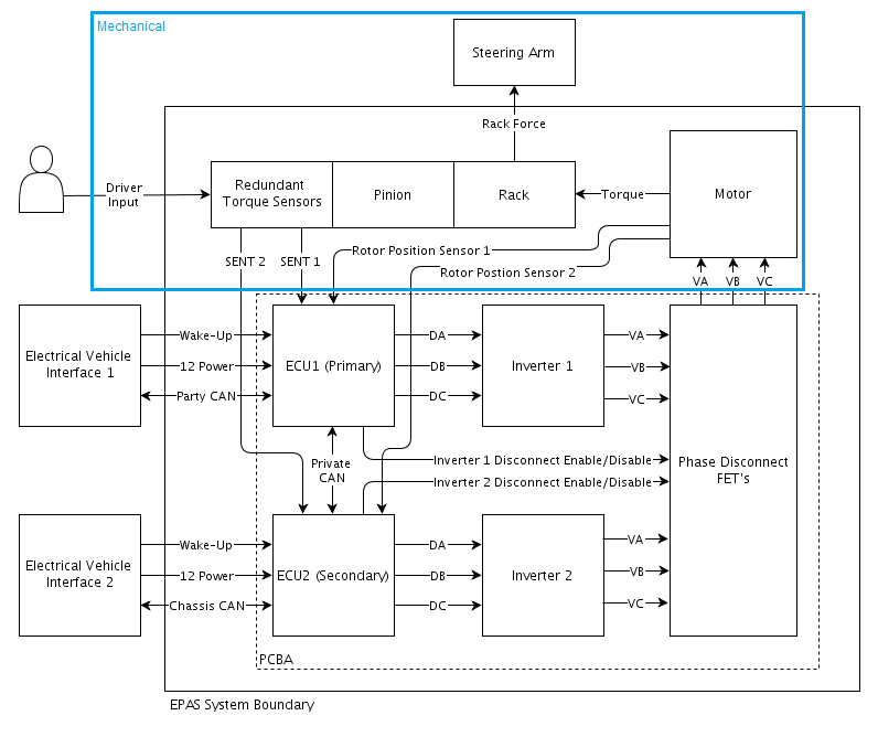
The steering rack comprises a rack and pinion gear, to which the intermediate shaft is connected. The EPAS3 features an electric motor that attaches through a belt drive to a recirculating ball mechanism to actuate the rack. This design has low friction and very little slip, but the precisely set tension of the belt means the motor cannot be serviced in the field. The controls of the electric motor are redundant. The EPAS3 system has built-in redundancy in the form of two ECUs, inverters, and a double set of wiring. There is one primary ECU and one secondary ECU. The secondary ECU serves as the backup to the primary ECU. Both ECUs have their own torque sensor and circuit board to drive the motor. The primary controller communicates via the Party CAN, and the secondary controller communicates via the Chassis CAN. Both controllers also communicate with each other via an internal private CAN. Important input to the controls are the steering wheel angle, input shaft angle, input shaft torque, and motor angle. The primary controller and the secondary controller are powered by the front vehicle controller (VCFRONT).
 |
|---|
|
| Steering Rack Components |
Steering Rack and Pinionlink
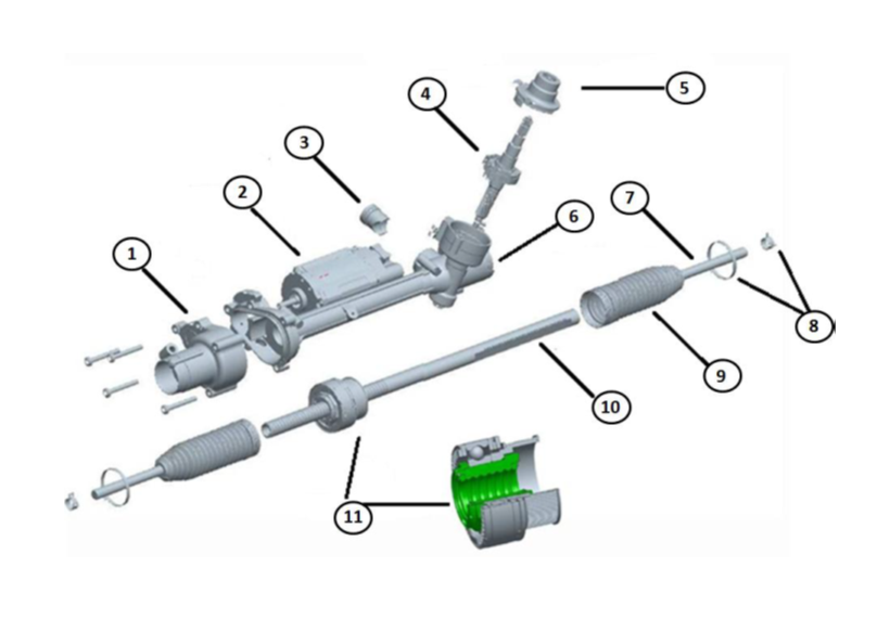
EPAS3 consists of a housing with an internal rack and pinion. The yoke presses the rack against the steering pinion to keep the clearance constant and play-free. A one-time adjustment of the adjusting screw on the yoke is done at the manufacturer. This screw may not be readjusted in the field. The rack and pinion gear transforms the radial movement into a linear movement.
 |
|---|
| 1. End Housing (Belt Drive And Ball Screw) 2. Motor 3. Yoke 4. Input Shaft / Pinion Assembly (Including Torque Sensor) 5. Cover 6. Housing 7. Tie Rod 8. Clips 9. Rubber Bellows 10. Rack Bar 11. Ball Screw Assembly |
| Steering gear internal |
Torque Sensorlink
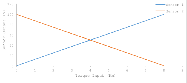
The torque sensor measures the steering torque the driver exerts on the steering wheel. It is located at the input shaft. Consists of a tuned torsional spring and 4 hall effect sensors. The sensors measure the twist of the spring and calculate the input torque from this. The spring has a mechanical stop that solidly connects the input shaft to the pinion when it reaches the end of its travel. The sensors work in pairs, like the pedal position sensors; they are oriented inversely so that when one reads 100% the other reads 0% and vice-versa. If there is a mismatch from expected behavior then a plausibility error is thrown. There are 2 such pairs of sensors for redundancy. Below is a visual explanation of how the plausibility check works. If either pair fails this check, the other is used and an error is thrown to warn of the malfunction.
 |
|---|
 |
|---|
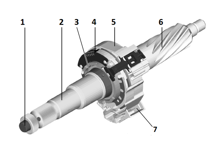
| 1. Torsion Bar 2. Steering Input Shaft 3. Magnet Ring 4. Sensor Module 5. Clock Spring 6. Steering Pinion 7. Electrical Connector |
| Torque Sensor |
Motor and EPAS3 ECUlink
The EPAS3 Electronic Control Unit (ECU) is a sealed unit mounted on the motor. It houses the microprocessor and the output stage for the motor. The servo motor is mounted to the rack with the housing of the servo end.
 |
|---|
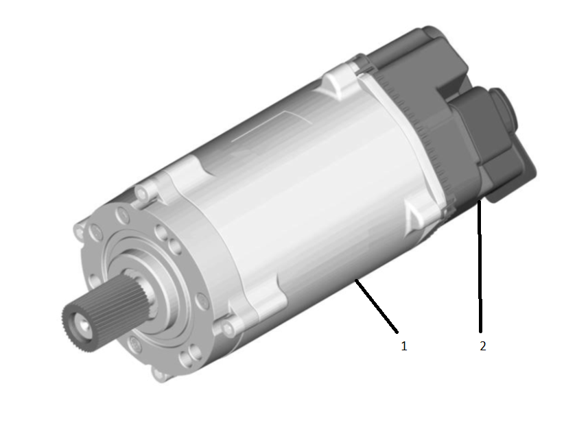
| 1. Motor Unit 2. Electronic Control Unit (ECU) |
| Motor |
Ball Screw Assemblylink
The radial drive movement of the servo motor is converted into a linear movement of the rack via a toothed belt and recirculating ball gear.
 |
|---|
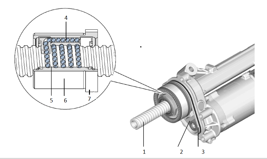
| 1. Rack 2. Toothed Belt 3. Toothed Wheel 4. Ball Return Channel 5. Ball Chain 6. Ball Recirculation Nut 7. Toothed Wheel |
| Ball Screw Assembly |
Tie Rodslink
The tie rods are the mechanical connections between the steering rack and the knuckles. They consist of two ball joints on either end and are adjustable in length via a threaded rod between the two joints to adjust for front toe. The ball joint connected to the rack, together with the threaded rod, is referred to as the inner tie rod. This part is not serviceable. The screw-on ball joint which connects to the knuckle is referred to as the outer tie rod and is serviceable.
Specificationslink
Electric Power Assisted Steering Steering Racklink
The steering rack electric motor is a three-phase, brushless motor known for good reliability and power density characteristics.
EPAS3 Signals Requirementslink
| Signal Name | Signal Type | Switch Type | Signal Attribute |
|---|---|---|---|
| KL15 | Analog | 4~26.5V | Wake-up signal |
| CAN High | CAN | 0~5V | High speed CAN |
| CAN Low | CAN | 0~5V | High speed CAN |
Main Power Operating Voltagelink
| Voltage Range | Status | System Function |
|---|---|---|
| 0 ~ 6V | Low voltage | All functions disable |
| 6 ~ 26.5V | Communication enable | CAN communication / diagnosis enable |
| 8 ~ 18V | Assist enabled | / |
| 9.5 ~ 17V | Normal operation | Normal power assist |
| 8.0 ~ 9.5V 17 ~ 18V |
Reduced performance | May limit power assist |
| 18 ~ 26.5V | Over voltage | May limit power assist |
Operating Currentlink
| Condition | Spec |
|---|---|
| Sleep Draw @ input torque 0, DC 12.6V, RT | 125 uA |
| Standby Mode @ input torque 0, DC 12V | 500 mA |
| Maximum input current @ maximum motor torque | 95 A_RMS |
Theory of Operationlink
General Operationlink
The steering wheel is the main control for the driver to control the direction of the vehicle. It is mounted on the steering column. Force applied by the driver translates into a moment of inertia around the axis of rotation of the steering wheel. This moment of inertia is passed through to the steering column and into the steering rack. In the steering column, the Steering Angle Sensor (SAS) reads the steering angle as applied by the driver, then compares it to the neutral position. This value is communicated to the primary control module (EPAS3P) via Party CAN and to the secondary control module (EPAS3S) via the Chassis CAN. The CAN message used for this is SCCM_steeringAngle. For more information on this CAN message, see the Serviceability section. The delta between what the EPAS3 estimates to be straight ahead by inputs from the Electronic Stability Program (ESP) and the angle measurement of the SAS is calculated as the applied steering angle offset. This value is added to the steering angle from the SAS.
In the input shaft of the EPAS3 steering rack, the input torque is measured. The steering input shaft and the steering pinion are connected with each other by a torsion bar. Two toothed rings for position measurement are fitted to both the input shaft and the pinion shaft. When the driver exerts a steering torque on the steering wheel, the torsion bar twists. The torsion bar is a calibrated spring, and from the difference in rotation between the input shaft and the pinion shaft, the torque can be calculated. The torsion bar spring rate is very high, and therefore the difference in movement between input and pinion shaft is very low. This is not noticeable as play by the driver.
 |
|---|
The EPAS3 ECU is pre-programmed with vehicle data and operating parameters with which to calculate the motor drive current, based on signals sent by the torque sensor and CAN data signals from other vehicle systems. These include the selected steering feel mode and vehicle speed.
Adjustments can be made by the driver to the steering feel / sensitivity using the touchscreen by navigating to: Controls>Driving>Steering Mode.
| Mode | Description |
|---|---|
| Comfort | More assistance. Reduces effort to turn the steering wheel, making it lighter to the touch. |
| Standard | Best compromise between steering effort and feel in all conditions. |
| Sport | Least assistance. Increases effort to turn the steering wheel, giving it a “sporty” feel. |
Dependent on the drive current calculated by the EPAS3 ECU, the electric servo motor generates a torque, which is transmitted by a toothed gear arranged on the motor shaft via a toothed rubber belt to the recirculating ball gear. In the recirculating ball gear, the ball chain is led back through an internal ball return channel in the ball recirculation nut. The rotation of the recirculating ball gear causes the rack to move to the left or to the right. The tie rods and the outer ball joints are arranged at the ends of the rack. They transmit the movement of the rack to the road wheels.
The effective steering power at the rack is the sum of the power applied at the steering wheel and the power of the steering assistance supplied by the servo motor.
EPAS3 is energy efficient and can be used for self-driving. It is also capable of turning the front wheels without any steering wheel input. Because of the mechanical link between the rack and the steering wheel, this will cause the steering wheel to rotate.
Active Returnlink
The active return function controls the self-centering force in the steering system. The self-centering ability in a vehicle is determined by the caster angle of the front wheels. Active return assists this ability. Self-centering can be noted when releasing the steering wheel while driving thru a corner. The steering wheel will return to center by itself. As the active return function of the electric power steering reacts sensitively to small calibration errors of the steering angle sensor, an algorithm is integrated in the software that determines the adjustment error during the drive over a longer time period for compensating it. This adjustment error is the applied angle offset.
Applied Angle Offsetlink
The EPAS3 does not have an internal absolute position sensor and thus relies on the SCCM, which has an absolute encoder disk, to set the “0” point. The primary objective of this function is to compensate a calibration error of the steering angle sensor or to compensate for minor alignment issues, so that a vehicle pull can be prevented through the active return with a slow steering angle correction. The function calculates an angle offset to the SCCM “0” point. The EPAS3 applies the angle offset based on the previous power cycle. After the initialization, the rack tracks its angle internally (internalSAS). This applied offset will show up as a difference in steering angle between the SCCM and the EPAS3. The goal of the offset is to make it so that the vehicle drives straight when the steering rack angle is 0. High applied offsets can indicate alignment issues, and the applied angle offset must be cleared after bringing alignment into spec.
- EPAS3P/S_appliedAngleOffset indicates the applied offset the rack is actively using this power cycle. After every power cycle, if the calculated and applied offsets diverge by a large enough amount, then the new angle will be applied on the next power cycle. Max value possible is ±12.8 degrees.
This function relies on the following inputs:
- EPAS3 internal steering angle (internalSAS)
- EPAS3 external angle controller status
- Vehicle speed reported by ESP
- Wheel speeds reported by ESP
Pull / Drift Compensationlink
This function attempts to reduce the steering hand wheel torque that the driver applies while driving in a straight line. This function aids the driver by compensating for the accumulated effects of various factors, such as road crown, that contribute to the pull / drift of the vehicle. This is achieved by the application of a counter torque from the EPAS3 system. The vehicle will drift less when the driver's hands are taken off the steering hand wheel, and steering straight ahead holding effort is reduced.
There are two sub-compensation components: pull / drift long term compensation and short term compensation.
-
Long term is designed to learn very slowly and is always applied when driving at speed. It is meant to compensate for drift and pull introduced by chassis asymmetries such as alignment and tire pressure. Long-term compensation torque usually changes less than 0.1Nm in a minute at steering wheel level.
-
Short term is designed to learn quicker and is only applied when driving straight at speed. It is cleared when steering high angles and during Autopilot. Short term is meant to compensate quick change of external disturbances such as change of road crown or side wind. Short term could change as much as 1Nm in 10 seconds at steering wheel level if facing a strong disturbance.
This function relies on the following inputs:
- EPAS3 internal steering angle (internalSAS)
- EPAS3 torsion bar torque as driver steering input
- ESP reported vehicle speed
- ESP reported wheel speed
- EPAS3 external angle controller status
Haptic Feedbacklink
This function is used with the vehicle’s driver assistance components to alert the driver that the vehicle has unintentionally crossed a lane marking. The feedback is provided through a high frequency vibration of the steering wheel generated by the steering gear. This does not have any effect on the overall steering feel or the current driving path.
External Angle Controllink
External Angle Control (EAC) is used to steer the vehicle using the Electric Power Assisted Steering System 3 (EPAS3) with the steering angle request (in degrees) from the interface DAS_steeringAngleRequest that is calculated by Driver Assistance System. After receiving the request, the steering gear makes a timely response to achieve the target path as planned by Driver Assistance System. This function is the interface between the steering gear and an external control unit to support:
- Lane keeping.
- Autosteer - Driver Assist System (DAS) functions.
- Autopark.
- Summon.
Motor torque is commanded to control the EPAS3 steering angle to match the DAS-requested steering angle when Autopilot is engaged.
External Angle Control is inhibited if any of the following are true:
- High vehicle road speed.
- User steering input is detected via a high torque steering input.
- Motor assistance detected a level too low.
- Steering angle suspected to be inaccurate.
- Differences between desired and actual steering rack angle position.
- Defined inputs from CAN (DAS, ESP, Gateway (GTW), Electronic Park Brake (EPB), SCCM).
The system will indicate a fault if any of the following are true:
- CAN error resulting in BUSOFF condition.
- MIA conditions on CAN.
- Invalid CAN data.
- LOAD_SHED detected on GTW.
This fault state is a latching state and requires a power cycle to clear.
Hands-On Detectionlink
The EPAS3 will monitor torsion bar torque to determine the level of driver interaction with the steering. The level of hands-on detection is set by evaluating the amount of torsion bar torque exceeding a calibrated threshold for a calibrated period of time.
There are 4 levels of EPAS3P_handsOnLevel and EPAS3S_handsOnLevel:
| Level | Description |
|---|---|
| Level 0 | No driver interaction and no effect on EAC |
| Level 1 | Light driver interaction and no effect on EAC |
| Level 2 | Moderate driver interaction |
| Level 3 | High driver interaction, cancels Autopilot and disables EAC |
Power Faultslink
When the power supply to one of the ECUs is interrupted, or when one of the CAN-Buses to EPAS3 is down, the steering system will still provide assist because the system is redundant. If the power supply is fully interrupted (either a full vehicle or the EPAS3 power), the driver can continue to steer the vehicle due to the mechanical connection between the steering wheel and the road wheels.
Warning: Greater effort than normal is required to turn the steering wheel in this situation.
Serviceabilitylink
Individual components cannot be serviced; the EPAS3 system must be replaced as a whole. Certain alerts can indicate with certainty that there are internal faults. However, it is important to note that this system is designed to be very robust. Before replacing an EPAS3 unit, it is important to understand if the failure mode that occurred is internal to the unit or may have been caused by issues with the data from the other systems it relies on.
The ECU can be interrogated for Diagnostic Trouble Codes (DTCs) and live data parameters using Toolbox.
Serviceabilitylink
Individual components can not be serviced; the system must be replaced as a whole. Certain alerts can indicate with certainty that there are internal faults, however it is important to note that this system is designed to be very robust. Before replacing an EPAS unit, it is important to understand if the malfunction that occurred is internal to the unit or may have been caused by issues with the data from the other systems it relies on.