Doorslink
Last updated: September 18, 2024
Door Handleslink
Exterior Handleslink
Overviewlink
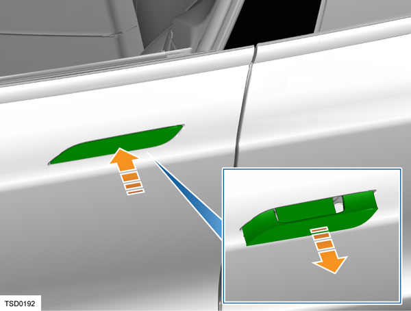
The exterior door handle sits flush with the door panel when retracted. Upon request, the handles extend out to allow the doors to be opened.
 |
|---|
2021+ Model S has electrically actuated exterior door handles that are normally flush with the body, but present themselves for use when needed. When retracted, the exterior door handle is flush with the door panel. Upon request, the handles extend out to allow the doors to be opened.
Componentslink
The handle is designed so that the present motion is actively achieved using a gear-reduction motor and mechanical linkage, which can overcome resistance from an iced-over handle. When the motor is reversed and removes pressure from the linkage, the handle retract motion is passively achieved using light spring pressure. Door handles automatically retract 60 seconds after the door is closed if they are not pulled. If 2021+ Model S is unlocked or a key fob is detected, lightly push a door handle to extend it.
Note: The door handles retract on spring pressure alone. If a hand or other object is in the door handle when the handle retracts, only light pressure is applied. The handle can easily be pulled back out to its fully extended position. This enables the hand or object blocking the handle to be removed.
 |
|---|
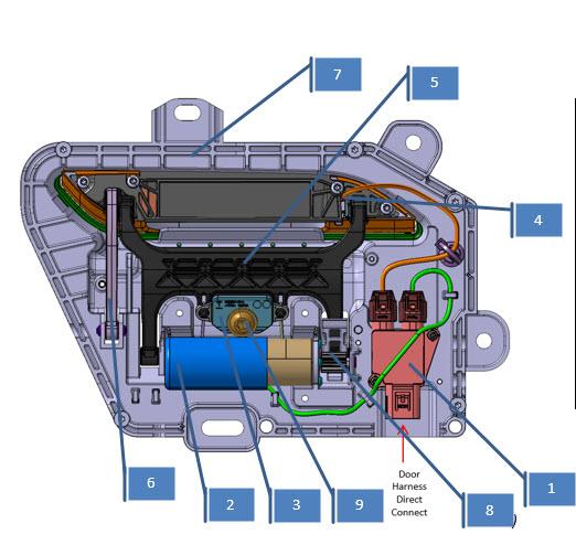
| 1. Connector Block 2. Motor 3. Push Block 4. LED 5. Handle Fork 6. Handle Link 7. Carrier 8. Paddle Gear 9. T40 Adjustment Screw 10. Fork Axle |
| 3rd Generation Door Handle, Overview |
 |
|---|
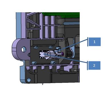
| 1. Magnet Holder + Magnet 2. Hall Effect Sensor |
| 3rd Generation Door Handle, Hall Effect Sensor and Magnet |
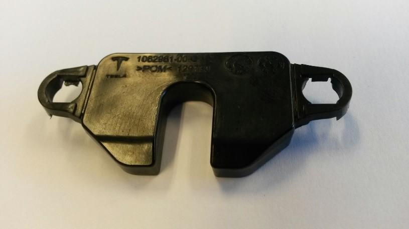
Connector Blocklink
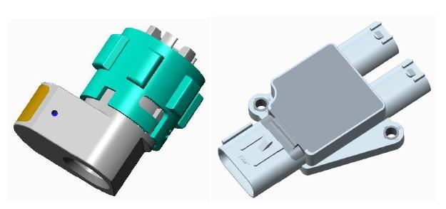
The connector block connects the LED and the motor to the vehicle harness. The three connectors are IPx9 rated. The connector block assembly also contains a hall effect sensor. The entire assembly is encapsulated in a low pressure mold to make it watertight. A connector with 6-pins connects to the door harness.
 |
|---|
| Connector Block |
Motorlink
The motor assembly consists of a motor, an adaptor plate, and a three-stage planetary gearbox. The motor is a DC motor with brushes and three pole-pairs. It is PWM controlled by the ECU.
The maximum PWM percentage that is applied is 80% (9.6V) but in most cases, less voltage is applied. The maximum current is hardware limited to 2.5A but software controlled to a lower limit by the ECU depending on the motion.
Push Blocklink
The push block is a plastic mold that is a slightly flexible. It acts as a spring to allow the handle axle to rotate slightly upon a push-to-present event.
 |
|---|
| Push Block |
LEDlink
The handle has an LED puddle light that illuminates the handle area and the ground below it.
Magnet Holder and Magnetlink
The magnet is located inside of a holder that is mounted to the handle shaft. Each handle position corresponds to a certain magnetic flux measurement value from the hall effect sensor. After calibration, the door handle can relate the measured value to a door handle position.
 |
|---|
| Magnet |
Hall Effect Sensorlink
The hall effect sensor is the only sensor in the door handle. It measures magnetic flux of the magnet on the axle shaft. The sensor is encapsulated in the connector assembly.
Electronic Control Unitlink
The motor, LED and hall effect sensor are wired to the ECU, which is external to the door handle. It is fitted onto the closeout panel on the dry side of the door.
Pinoutlink
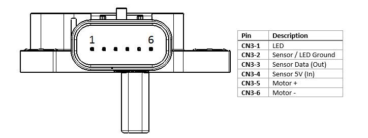 |
|---|
| Pinout, Top |
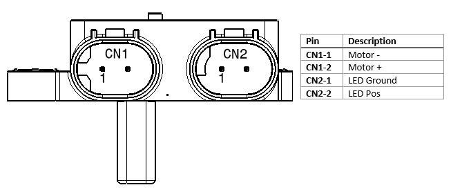 |
|---|
| Pinout, Bottom |
Operationlink
The door handle has three main positions: retracted (0%), presented (90%), and pulled (100%). These positions are measured by a hall effect sensor.
To start movement from one position to another, the handle needs to be in a known position. If the door handle is in an unknown state, it will not move to another state.
Both door handles on the same side of the vehicle communicate over LIN to the corresponding door module (DDM/PDM). The LIN bus speed is 19.2 kb/s. The door module is the primary node in the LIN communication and the door handles are secondary nodes. The door module sends commands to the door handles and the door handles respond with feedback signals.
The most important command the door module sends to the door handle is ‘Handle Position Command’, which can represent ‘No Change’, ‘Present Handle’, or ‘Retract Handle’.
The door handle receives this command and will actuate the handle accordingly.
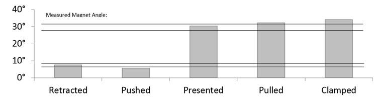
Door Handle Stateslink
The figure below explains the different door handle states and how they relate to the handle shaft angle. There are two angle ranges, which are the ‘Retracted’ position and the ‘Presented’ position.
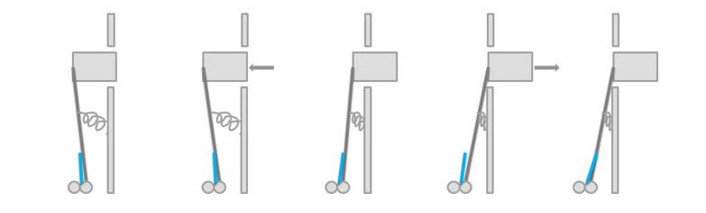 |
|---|
The table below explains how handle axle shaft angle relates to travel percentage, to motor state, and to hall sensor value.
 |
|---|
Calibrationlink
Since the door handle has continuous position feedback by means of a hall effect sensor, it needs a calibration routine like any other position controller in the vehicle (think of Falcon doors, seat track positions, and the Model X spoiler).
The calibration routine cycles through the entire range of positions and matches the position measurement values with known fixed positions (latched position for the Falcon doors, hall sensor for seat track position, and the hall effect sensor for the spoiler).
These positions are the clamped and the retracted positions.
- Clamped: This is the most outward position of a door handle. The motor pushes the handle outwards against its mechanical end where current starts to rise. This position is considered 100% handle position.
- Retracted: This is the most inward position of a door handle. It is the point where the 'push-to-present block' starts to touch the T40 screw. This is also the point where the hall effect sensor does not report a change in angle while the motor still spins. This point is considered 0% handle position.
Once the handle knows which hall effect sensor readings correspond to 0% and 100%, it knows all other positions in between, e.g. the presented position is considered 90% handle position.
When retracting, the motor stops later than the 0% position (around -5%) to leave room to push the handle.
The handle is self-calibrating in the vehicle. This way, the handle can compensate for carrier and door sheet metal warpage.
Sleep Modelink
The microcontroller will go to sleep if a sleep command is sent over LIN or if there is no LIN activity and the door handle is in the retracted position.
When asleep, the microcontroller can be awakened by LIN activity or by a handle push. By periodically waking up, sampling the sensor, then going back to sleep (at a rate of 10Hz), the microcontroller is able to detect the handle position to register the pushes. The hall effect sensor is switched off while the microcontroller is asleep and turned on when it wakes to take samples.
Interior Door Handleslink
 |
|---|
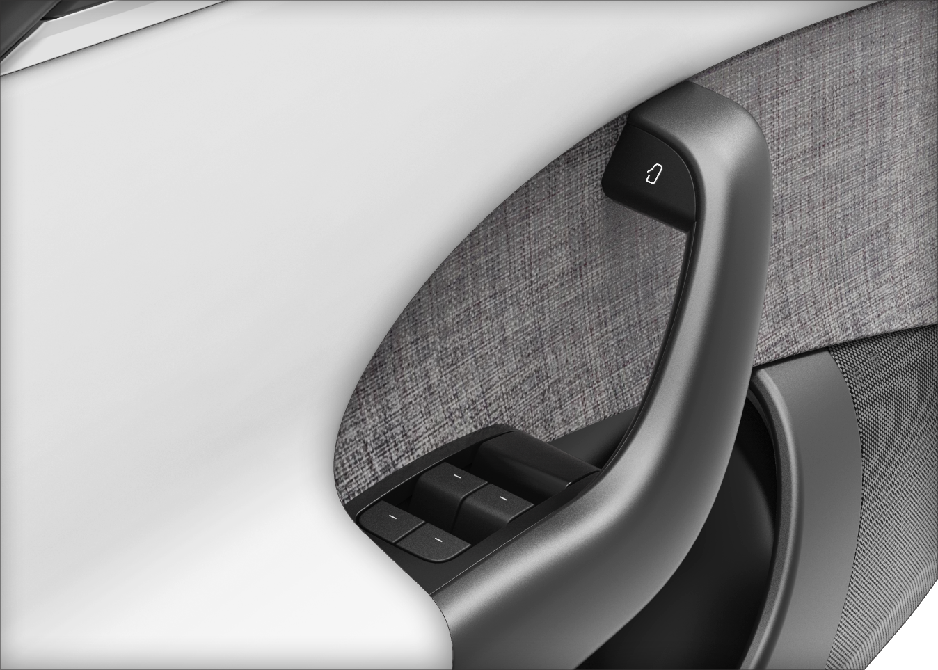
| The interior door force touch button |
The front and rear doors feature a force touch button on the handles that open the doors when engaged. The force touch button consists of * Capacitive sensor with haptic feedback * Dedicated ECU
When the user applies pressure to the force touch button, the capacitive sensor receives this input and provides a haptic feedback in the form of a vibration to confirm the input was received. The dedicated ECU then communicates to the corresponding left and right vehicle controller over LIN to release the latch.
Note
- If the ECU is replaced in service, the firmware on the ECU must also be updated.
- If the switch malfunctions or power to the front doors is not present, there is a release cable which acts as a mechanical backup and releases the latch.
- Enabling the child-protection lock prevents doors opening from the rear door interior release handles. The only exception is in the event of an airbag deployment, which unlocks all doors and overrides the child-protection locks.
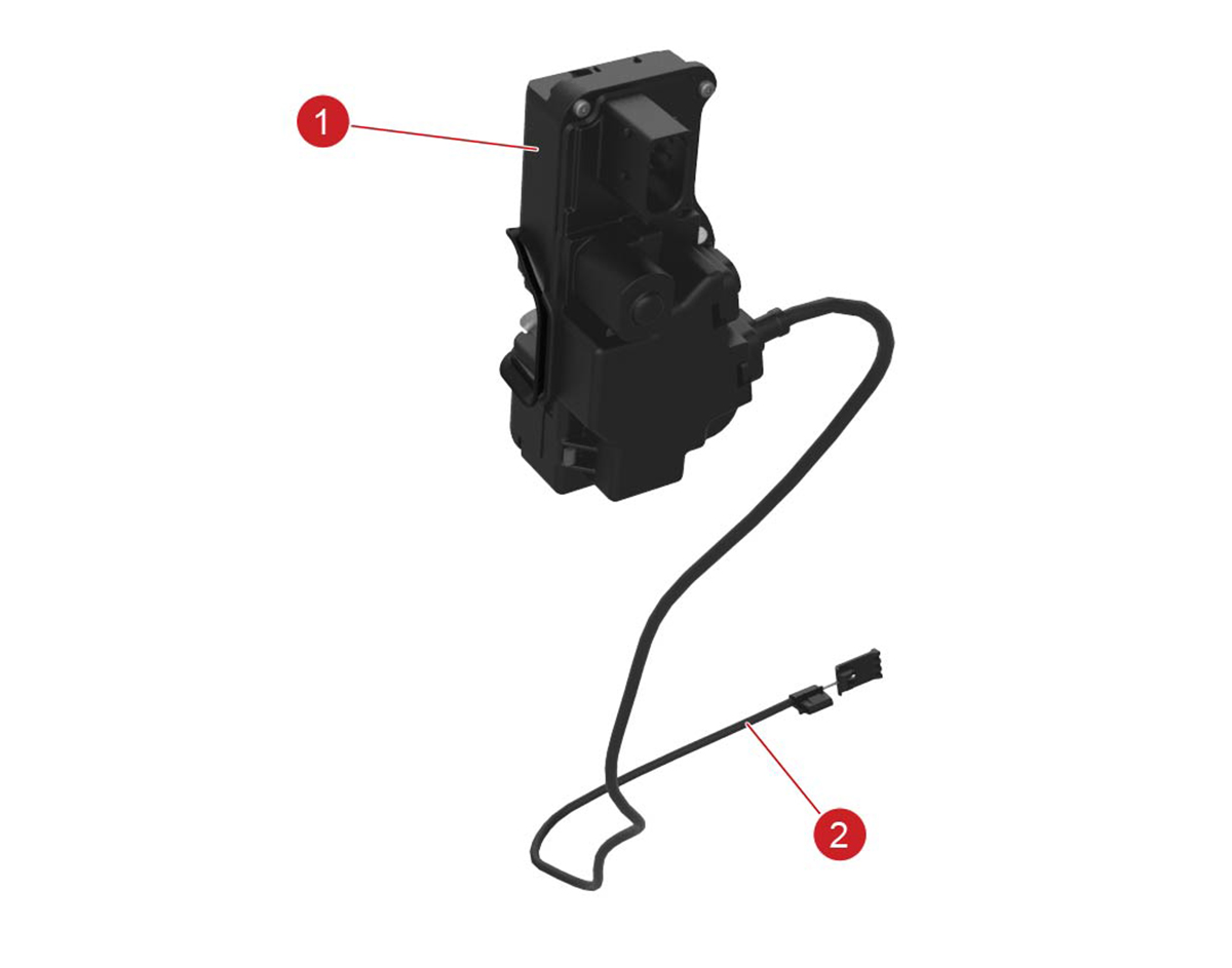
Door Latcheslink
Front Door Latchlink
 |
 |
|---|---|
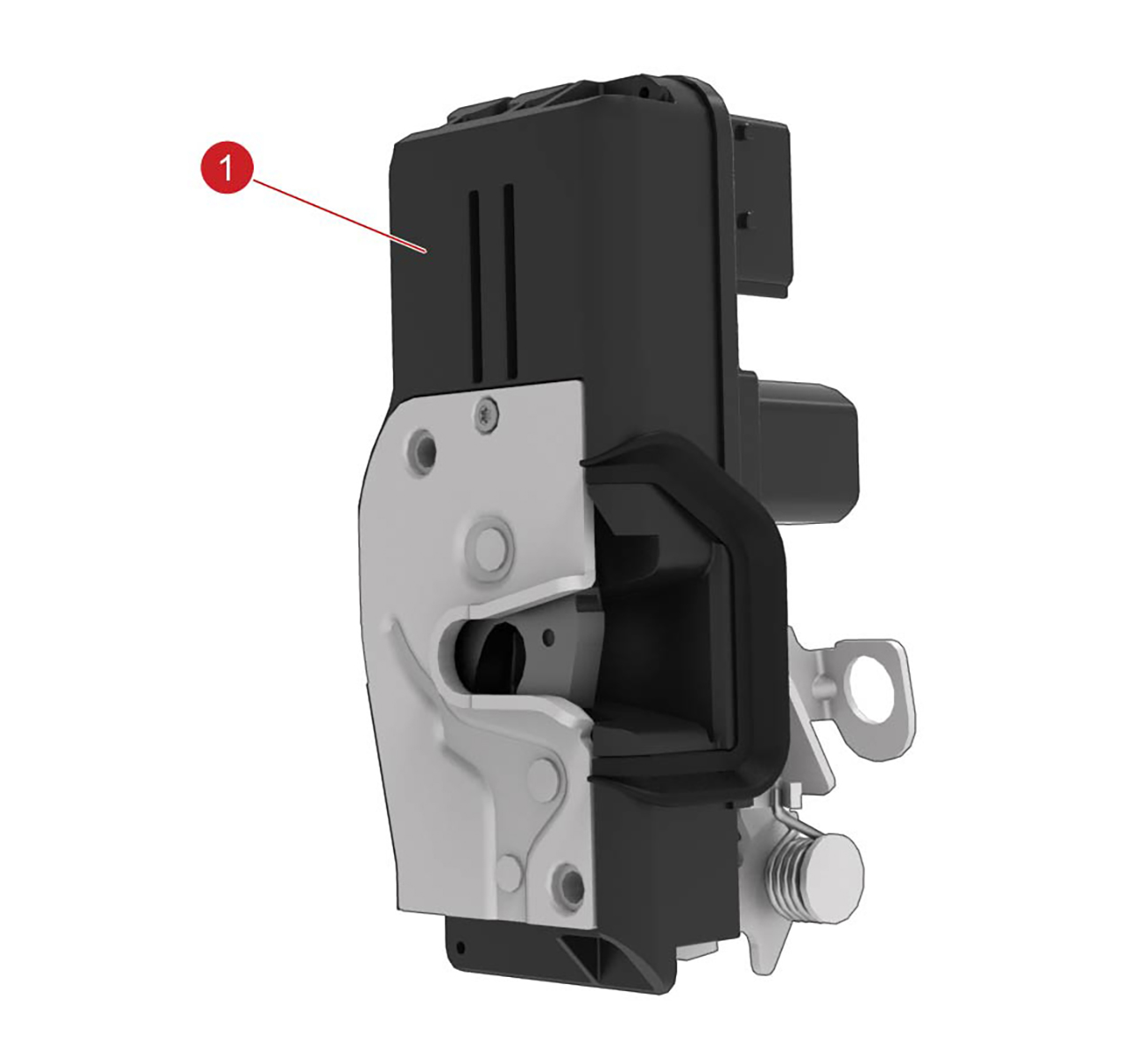
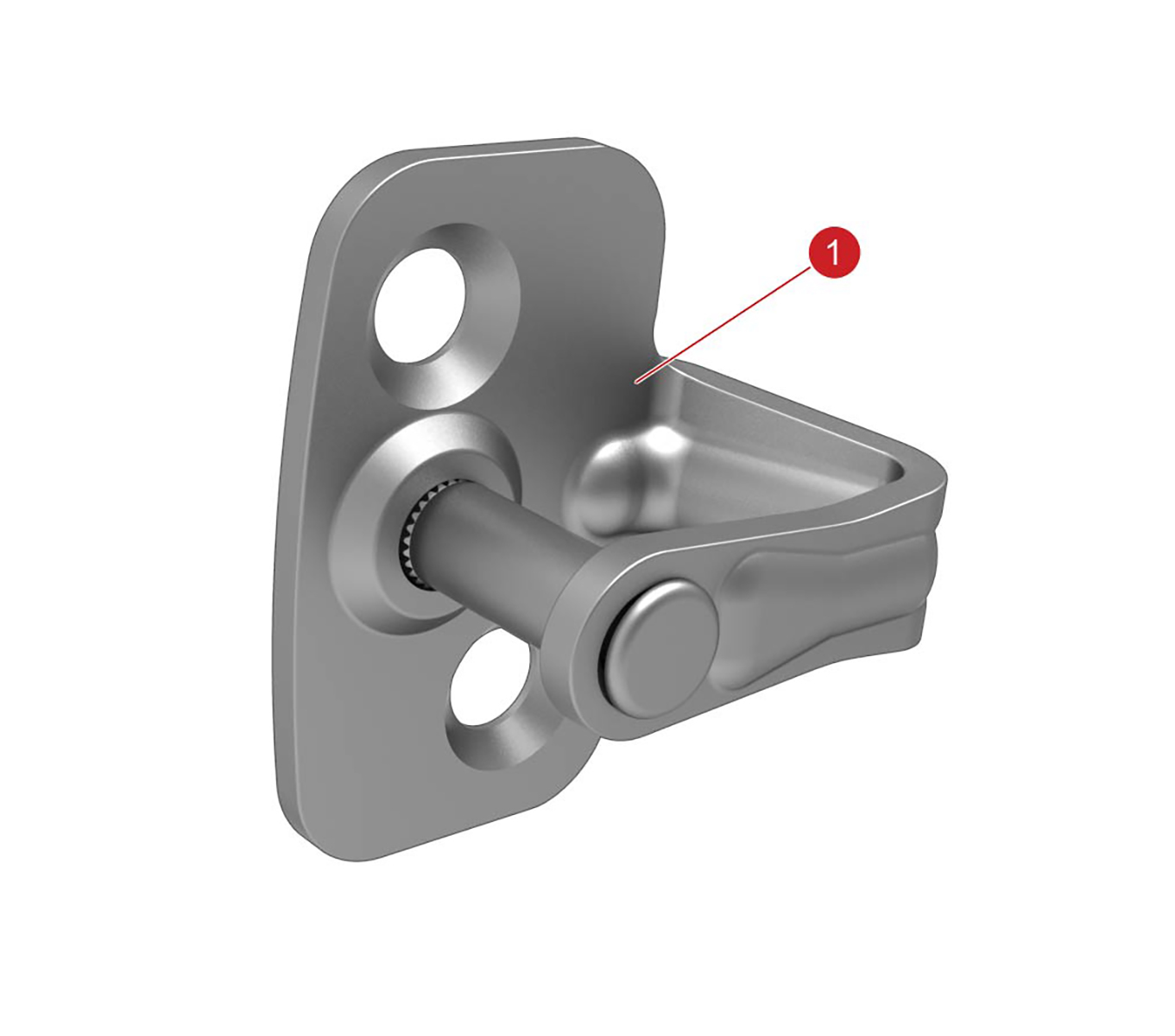
| 1. Front door latch | 1. Door latch striker |
The front door latches are located inside each door. The latch is primarily electric, but a cable is connected to the latch from the front door interior mechanical release handle to open the door in the event there is an electrical fault.
The front door latch striker is located on the B-pillar and can be adjusted in the Y direction for door flush or in the Z direction for closing effort. This prevents latch and striker misalignment.
Rear Door Latchlink
 |
|
|---|---|
| 1 . Rear door latch 2. Release cable |
1. Door latch striker |
The rear door latches are inside the rear quarter panels. The rear interior door handle button operates the latch switch.
The rear door latch striker is located on the rear edge of the door. The latch strikers can be adjusted for alignment.
The rear door latches have child locks, which can be enabled and disabled using the touchscreen.