Second Row - 60/40 Bench 7 Seaterlink
Last updated: October 10, 2024
Overviewlink
2021+ Model X has 3 different seating capacities:
-
A standard 5 person seating capacity with a driver and passenger seat in the front row and a three passenger bench seat with backrests that fold flat in the rear. The second row bench seat comes in two pieces, the 60% which is the left and center seating positions and the 40% which is the right seating position.
-
A 6 person seating capacity with a driver and passenger seat in the front row, two independent monopost seats in the second row and two bench type seats in the third row.
-
A 7 person seat capacity with a driver and passenger seat in the front row, a three person passenger bench seat in the second row and a two bench type seats in the third row.
2021+ Model X seats come with 3 different color options, black, white, and cream. The second row and third row seats do not have ventilation, but do have seat heating.
The seat sections are referred to as 40% (right-side rear seat), 60% (left-side and middle rear passenger seats), and 20% (middle rear passenger seat).
Coverslink
Component Descriptionlink
2021+ Model X seats are available in cream, white, and, black polyurethane (PUR). This material is a leather alternative. When surfaces of the seat back contact one another, one side is a cloth material, while the other side is PVC, another type of artificial leather that has a rougher feel and is used in areas that is not typically touched by customers. This is to reduce noise issues that are typical when PUR rubs against itself. Along with 3 colorways, there is an option between covers for a long range variant, and covers for a performance variant. The second row seats are perforated on the centermost panels. Performance variant second row seats have also have perforation on the inner bolsters. Where the inner bolster meets the outer bolster, there is piping for added detail and luxury.
Theory of Operationlink
2021+ Model X second row seat covers are secured to the foam using a combination of hog rings and hook-and-loop fastening strips. Then sandwiching the foam, the cover is attached to the upholstery support allowing the seatback to maintain shape prior to attachment to the seat frame. There is also stitch detailing within the seat to help form the shape around the foam.
Serviceabilitylink
Cleaninglink
Cleaning PUR seats with some conventional cleaners (especially alcohol-based) can cause performance and appearance degradation. Do NOT use products containing bleach (sodium hypochlorite). It is therefore important to clean seats with only approved cleaners. Below is a list of approved cleaners:
- Clorox NON Bleach Disinfecting Wipes
- Formula 409
- Seventh Generation NON Bleach Disinfecting Wipes
For CREAM PUR ONLY, isopropyl alcohol is the strongest solvent that can be used without damaging the seat material. Moisten a soft cloth with warm water and isopropyl alcohol and gently wipe the stain in a circular motion.
Warning
Isopropyl alcohol should not be used on Black or White PUR.
Servicing Coverslink
Hog rings must be installed using hog ring pliers to crimp the ring in order to securely fasten the cover to the foam.
Hog rings are a consumable part, as with every removal they need to be cut.
Craftsmanship is extremely important when dealing with and installing covers to ensure that there are no wrinkles or puckers in the material.
Foam/Padlink
Component Descriptionlink
The seat foam, also referred to as the seat pad provides comfort and stability to occupants.
Serviceabilitylink
If the seat foam and covers have not been installed appropriately it can feel or look as if the seat is missing foam or that the foam has collapsed. Because the foam is sandwiched between the cover and upholstery support, it is possible that it could have been misaligned during installation. In some rare cases, the way in which a customer ingresses or egresses from the vehicle can apply pressure on the outmost edge of the cover and foam, causing the foam to get caught on the upholstery support and not maintain it's full shape. This can be resolved by refitting the cover and foam.
Controllerlink
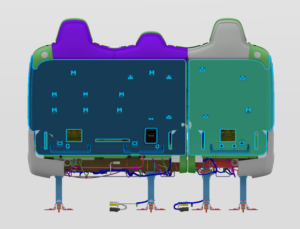
Located underneath the seat cushion of each seat is a seat controller that controls all electromechanical function. This includes, seat buckle, occupancy sensors, and heating pad. The 60% controller is Body Controller Seat 2nd Row Left (BCS2L) and the 40% is the Body Controller Seat 2nd Row Right (BCS2R).
Seat Heatlink
Component Descriptionlink
2021+ Model X second row has heating elements in each of the cushion seating positions as well as the backrests.
The seat heater is made up of the following components:
- High side driver
- Pulse width modulation (PWM)
- Negative temperature coefficient (NTC) thermistors
- Resistive pad
The heating element, or resistive pad, is located only in the center panels of the seat back and seat cushion, the heating element is not located in the side bolsters.
Theory of Operationlink
There are 3 heating temperature targets for the seats (low, medium and high). Target temperatures for both the cushion and the backrest are:
- Low (Setting 1): 28C or 82F
- Medium (Setting 2): 44C or 111F
- High (Setting 3): 60C or 140F
The seat heaters utilize PWM at 1Hz in order to reach the desired target temperature. This means pulsing the voltage at a controlled frequency. The duty cycle (width of the pulses) will be increased if the temperature read by the NTC is below the target temperature, the duty cycle can be increased all the way up to 100%, providing up to 16V. When the temperature read by the NTC is higher than the target temperature, the duty cycle can be decreased all the way to 0% providing no voltage. Due to this PWM, the voltage at the seat heater is constantly changing and varies due to ambient temperature and heat setting level.
Current travels through the resistive pad generating the heat. This resistance remains constant with a functioning seat heater.
The NTC is located only in the seat cushion, not the seat back. It is connected to 5V through a resistor on the body controller. As the temperature of the seat increases, the resistance on the NTC lowers and the voltage read at the controller goes down. If the thermistor is disconnected, the voltmeter will read 5V or 0V depending on where the disconnect occurs. At around room temperature, the voltage at the NTC should be around 3.6V.
Communicationlink
The seat heater communicates via vehicle bus (VEH). The seat cushion and the 60% seat back is controlled by the left vehicle controller (VCLEFT). The seat back fo the 40% seat is controlled by the right vehicle controller (VCRIGHT). Below illustrates which seat heater positions communicate on which vehicle controller.
Serviceabilitylink
The seat heater resistive pad is integrated into the seat cover and is therefore not serviceable.
The temperature felt at the surface of the seat, depends on an occupant sitting in the seat. Compressing the foam and trim with an occupant sitting in the seat allows for the occupant to fully feel the temperature provided by the seat. Factors such as a heat soaked interior, body heat from someone sitting in the seat, direct sunlight and ambient air temperatures can play a big role on the temperature readings at the surface of the seat cover.
Occupancy Sensinglink
Component Descriptionlink
Each seat in the second row contains an occupancy sensor and resistive pad, also referred to as the seat belt reminder (SBR). The occupancy sensors are located in the seat cushion. The occupancy sensors are switches distributed throughout the cushion connected in both parallel and series.
Theory of Operationlink
Occupancy sensing for the second row communicates to VCLEFT. The sensor itself is a simple resistive pad that can be tested with a multimeter. Occupied, the resistance should read 1kOhm. Unoccupied, the resistance should read 11kOhm.
Serviceabilitylink
Occupant sensors are distributed throughout the cushion to help prevent situations where small items might trigger the seat belt reminder indicator. At the time of publishing this document, the resistive pad, or seat belt reminder, located in the second row cushion is not a serviceable component. This is due to the infrequency of which this part needs to be replaced as well as current production capability.
Framelink
Component Descriptionlink
The second row is comprised of two separate backrest frames. The 60% and the 40%. The 40% contains the right hand second row passenger and the 60% contains the left hand and center passenger positions, with the center position being referred to as the 20%. For 2021+ Model X, these structures are stand alone frames with the seat cushion bench being one piece that sits atop the Ancillary Bay.
Theory of Operationlink
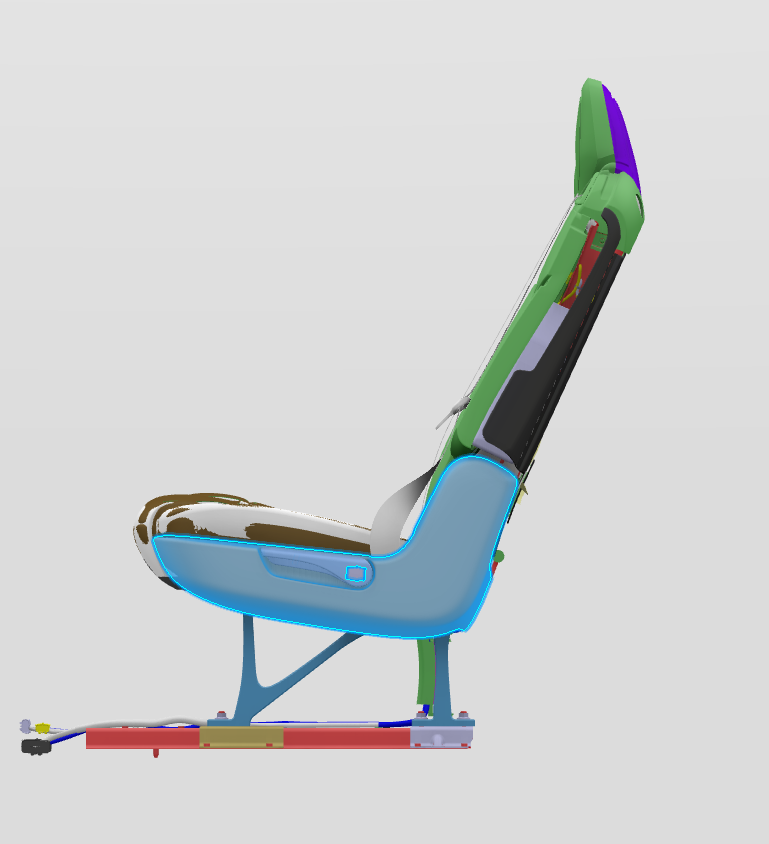
The frame allows for the backrest to pivot about the bottom edge in order for the backrest to fold flat as well as recline into a comfort position. the seat back comfort adjusts +8/-6 degrees relative to design position. Once past +8 degrees from design position, the seat back falls into a fold flat state. For the 7 seat variant of the bench seats, there is an added portion on the frame that causes the seat back to stop at a 45 degree angle allowing the seat to go into easy entry. 7 Seat second row frames have the ability to move forwards and backwards along the track. The rearmost 100mm of the track is considered comfort adjust. Utilizing the manual track lever, the seat can move in 1 of the 10 positions in comfort adjust. the forward most 170mm of the track is considered the easy entry position, in easy entry the seat can be in 1 of 2 positions.
Serviceabilitylink
A spring is located on the outboard side of the seat at the axis of rotation for the seatback to fold forward. This spring helps pop the seatback forward but does not cause the seatback to dump in a fold flat position.
Because the frame is a moving part, it can be the culprit to some noise issues. In these instances be sure to check all mating points to the body as well as the hinge point (axis of rotation).
Trim/Plasticslink
Component Descriptionlink
To limit confusion during diagnosis and when talking about the seats, trim is defined as the hard plastic parts on the seat. Seat pads and covers (the textile or leather seat material) are considered seat upholstery and should be referred to as such.
In addition to the components shown in the image above, the following pieces are also considered:
- Back panels
- Side Shield
- Escutcheon
- Cushion Support
- Plastic Covers
Theory of Operationlink
Back Panelslink
The back panels for the second row are plastic components that conceal the wiring harness. The Back Panel provides structured support to the seat when it is in the fold flat position. The back panels also have a cut outs for child seat tethers. Removing the back panel will allow access to inspect components like the recliner mechanism for first steps of diagnosis. The back panel is covered by a soft trim for cosmetic purposes, this trim cover will differ based on if the vehicle is long range or performance.
 |
|---|
| Back Panels |
Side Shieldslink
The 60% and 40% seat backs can be adjusted via the lever located on the outboard side shield. This lever allows the seat to fold flat or adjusts the seat back into various positions for comfort adjust.
 |
|---|
| Side Shields |
Escutcheonlink
The escutcheon is the plastic bezel in which the seat belts feed through the backrest. All 3 seating positions have retractors incorporated into the second row and the escutcheon acts as protection to the cover.
 |
|---|
| Escutcheon |
Cushion Supportlink
Located on the front of the frame underneath the foam and covers, a plastic cushion support is mounted in order to help give shape to the cushion foam and allow the front portion to sit higher than the rear cushion foam.
 |
|---|
| Cushion Support |
Plastic Coverslink
There are various covers on the second row seats. A covers on both the inboard and outboard portions of the seat conceal the recliner mechanism located at the junction of the seat back frame and cushion frame. B covers are located on the inboard side of the seat. Each B Cover has an inner and outer component to conceal the frame. There is a recliner cover on the outboard side of the frame that conceals the frame with the help of the side shield. Finally, located on each riser are two plastic riser covers, these covers conceal the seat wiring harness along with the track locking mechanism.
Actuatorslink
Component Descriptionlink
The 40% seat has 2 actuators while the 60% has 3. The 40% has an easy entry recliner actuator and an easy entry track actuator. The 60% has an easy entry recliner actuator, a recliner release actuator and an easy entry track actuator.
 |
|---|
| Actuators |
Theory of Operationlink
40% EZ Entry Track Release Actuatorlink
The 40% easy entry track release actuator is located in the seat back rest. This actuator is connected to an easy entry track release cable assembly. This cable assembly connects to both the inboard and outboard side of the track. Because the actuator pulls up on the cable assembly, the tracks are released simultaneously. The track release cables attach to the upper track allowing the seat to move from comfort range to easy entry range. The EZ Entry actuators only allow for easy entry functionality, it is possible for easy entry to function but the manual movement of the track may not. It is also possible the manual movement of the track may function but the easy entry function of sliding the seat forward may not.
 |
|---|
| 40% EZ Entry Track Release Actuator |
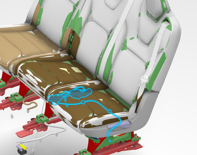
40% EZ Entry Recliner Release Actuatorlink
The 40% easy entry recliner release actuator is located in the seat cushion. This actuator is connected to a recline splitter cable assembly that has a single cable which releases the entire seat back. The recline splitter box allows the manual track handle to connect to the same cable which releases the entire seat back. The easy entry recliner release actuator is also connected to a cable that splits between the inboard and outboard side of the back rest. These cables release an easy entry stopper assembly which prevents the back rest from traveling further forward than a 45 degree angle. Because there are 3 cables in total, it is possible for the seat back to release but not lock in the 45 degree position, this would likely be an issue with the cable assembly or the EZ Entry Stopper Assembly.
 |
|---|
| 40% EZ Entry Recliner Release Actuator* |
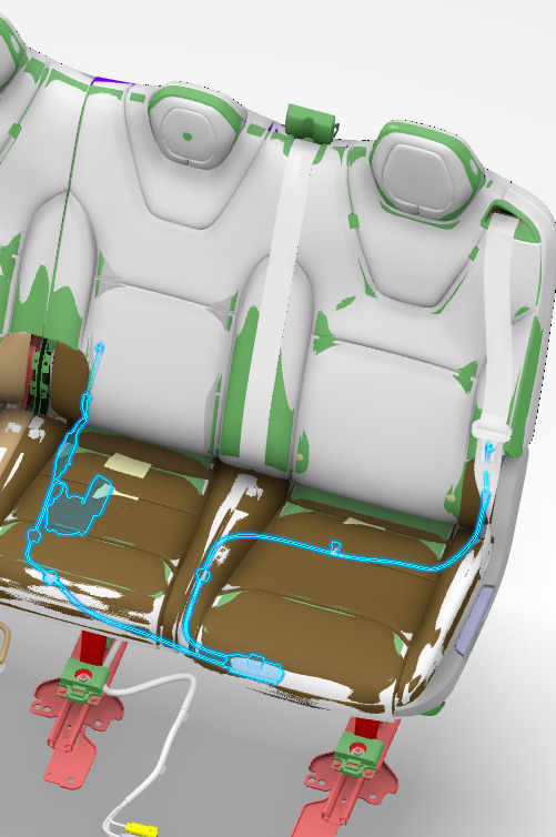
60% EZ Entry Track Release Actuatorlink
The 60% EZ Entry Track Release Actuator is located in the seat cushion. This actuator is connected to an easy entry track release cable assembly. This cable assembly connects to both the inboard and outboard side of the track. Because the actuator pulls up on the cable assembly the tracks are released simultaneously. The track release ables attach to the upper track allowing the seat to move from comfort range to easy entry range. The EZ Entry actuators only allow for easy entry functionality, it is possible for easy entry to function but the manual movement of the track may not. It is also possible the manual movement of the track may function but the easy entry function of sliding the seat forward may not.
 |
|---|
| 60% EZ Entry Track Release Actuator |
60% Recliner Release Actuatorlink
Not to be confused with the 60% EZ Entry Recliner release actuator, the recline release actuator only releases the seatback allowing it to move freely. The actuator feeds into a splitter box who's endpoint is attached to the recliner mechanism located on the inboard side of the 60% seat. This actuator which pulls on the inboard recliner mechanism acts a supplemental support to releasing the inboard recliner mechanism, as the EZ Entry Recliner Actuator ensures that the outboard recliner mechanism is released. If the outboard portion of the seat back is released, but the inboard portion of the seatback remains locked in ride position, the issue is likely with the 60% Recliner Release Actuator.
 |
|---|
| 60% Recliner Release Actuator |
60% EZ Entry Recliner Release Actuatorlink
The 60% EZ Entry Recliner Release Actuator pulls on the EZ Entry Stopper rotating it about a pin and allowing the seat back to be locked into a 45 degree angle. The EZ Entry Recliner Release Actuator also feeds into the recliner release cable assembly. This is so that the EZ Entry Stoppers are triggered into place at the same time the seatback is released. If the seat is moving along the track in EZ Entry range but the seat back is not locking or unlocking from the 45 degree angle or the upright position, the issue is likely with the EZ Entry Recliner Release Actuator.
 |
|---|
| 60% EZ Entry Recliner Release Actuator |
 |
|---|
| 60% Recliner Release Assembly |
Fold Flat Function - Manuallink
Feature Descriptionlink
Fold flat refers to the position in which the seatback is completely folded down and laying on top of the seat cushion. Fold flat can occur on the 40% or the 60%. Along with fold flat, the seat back is able to recline +8/-6 degrees from nominal position to find a more comfortable reclining position.
Theory of Operationlink
The seat back gets into fold flat position through the use of the lever located on the outboard side shield. This same lever allows the seat back to adjust into one of the reclined positions for more comfort.
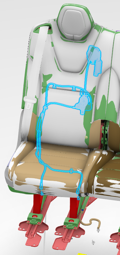
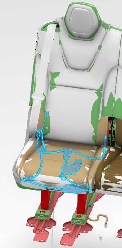
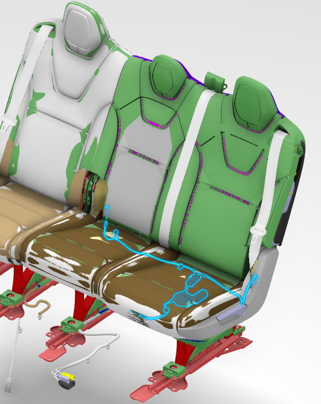
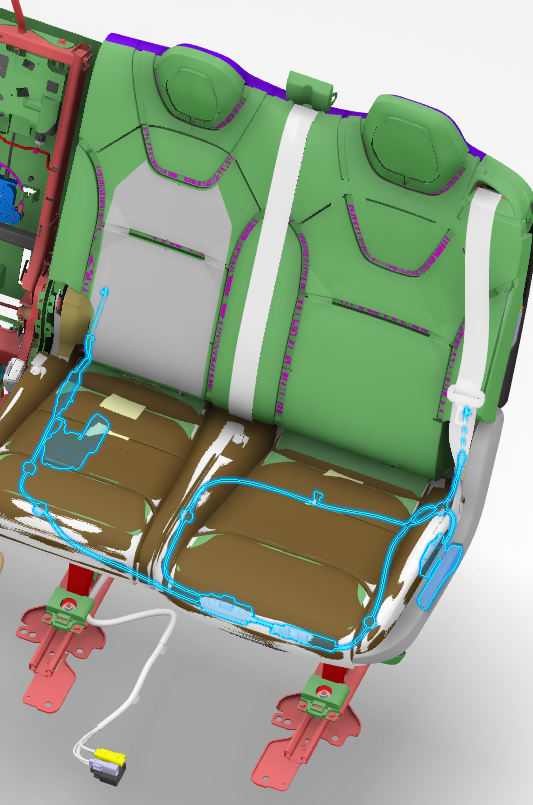
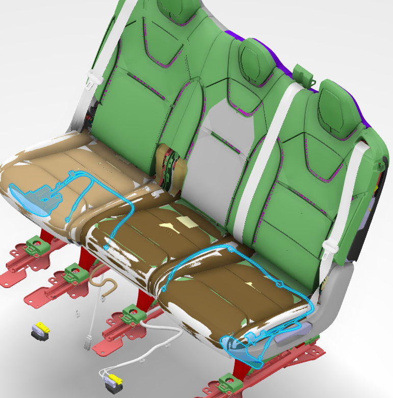
Cable Assemblylink
The lever located on the side shield is attached to a cable assembly that routes to a recliner splitter box. For 7 Seater, the lever manual cable and the EZ Entry Recliner Release actuator cables route to the splitter box. The output of the splitter box mates to the recliner mechanism on the outboard side for the 40% and on both the inboard and outboard side on the 60%.
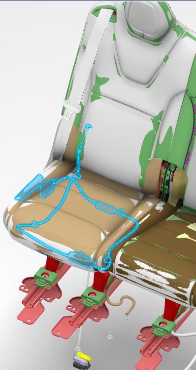 |
|---|
| 40% Manual Cable Assembly |
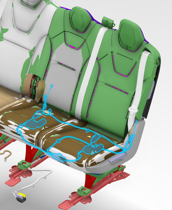
Because the 60% is a heavier seat back, recliner mechanisms are located on both the inboard and outboard sides. The cable system that pulls on the recliner mechanism must pull the cable on each side simultaneously. This is done with a recliner splitter box, the cable attached to the lever feeds into a splitter box that then pulls both cables on each recliner mechanism simultaneously.
 |
|---|
| 60% Manual Cable Assembly |
Recliner Mechanismlink
The recliner mechanism is a disc, lever and hard stop. The recliner mechanism is located where the cushion frame and back rest frame meet. At this junction a disc with teeth is welded into the frame and mates with another disc with mating teeth. When pulled down, the recliner lever releases the recliner disc and allows the seat back to be free moving. Located on the seat frame is a hard stop that prevents the seat back from traveling too far back.
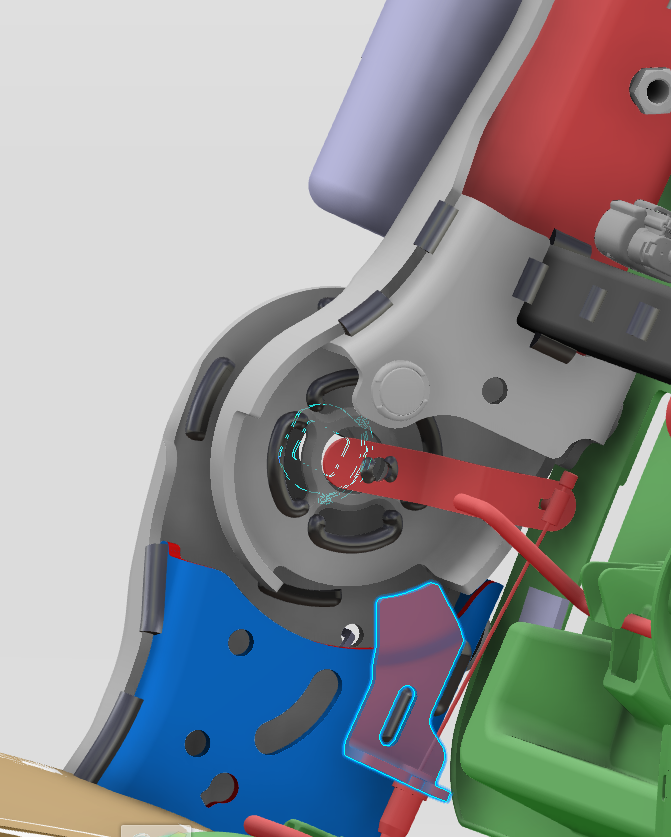 |
|---|
| Highlighted above is the seat back stopper for reclining the seat back |
| Recliner Mechanism |
Comfort Adjustlink
Feature Descriptionlink
Comfort adjust is the ability to move the seat forwards and backwards along the track using the manual track release handle. The rearward most 100mm of the track is considered comfort adjust zone and can move manually throughout this region to 10 different positions.
 |
|---|
| Manual Track Release |