Exteriorlink
Last updated: October 20, 2023
Aerodynamicslink
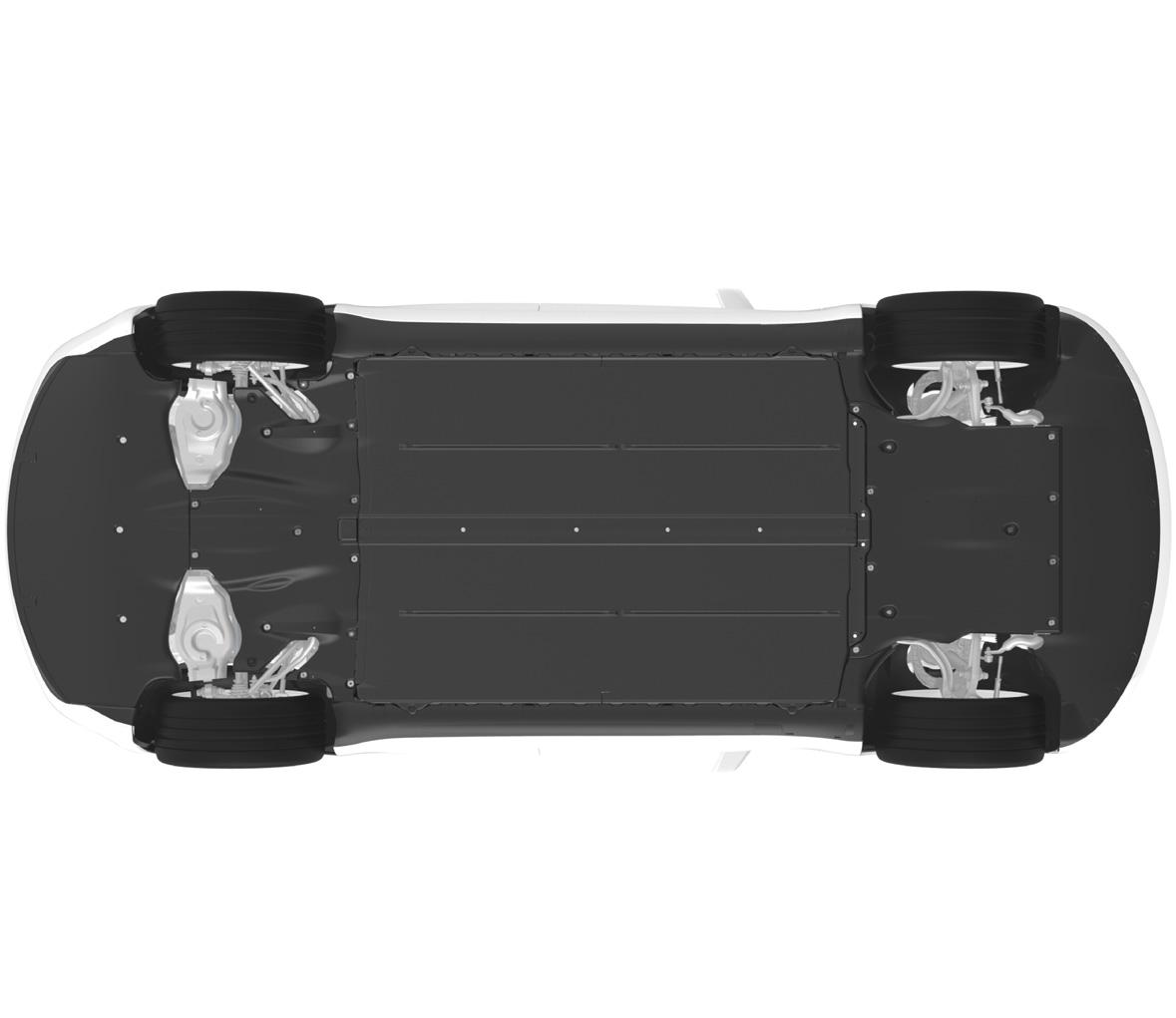
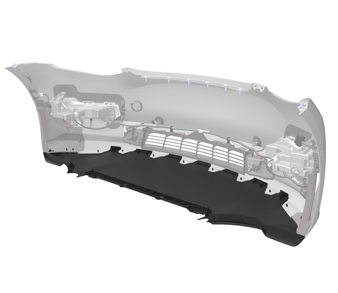
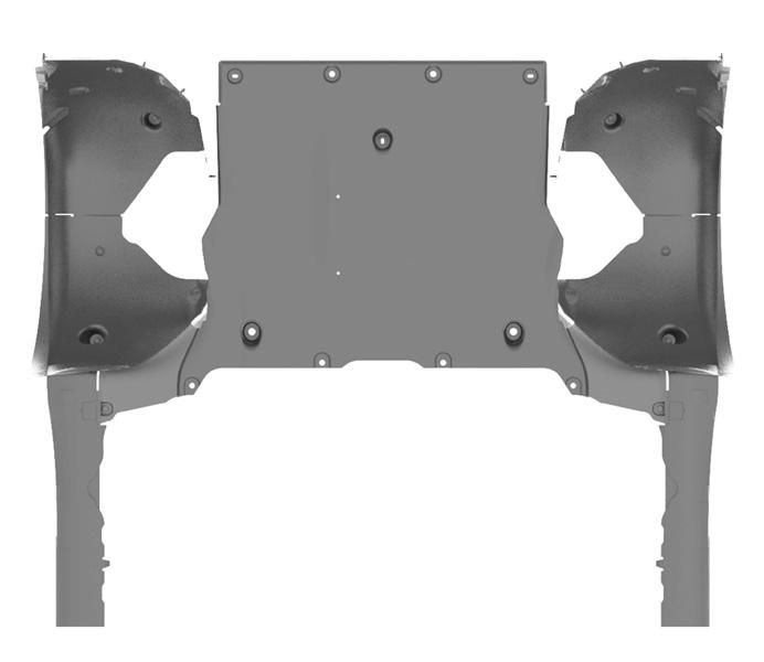
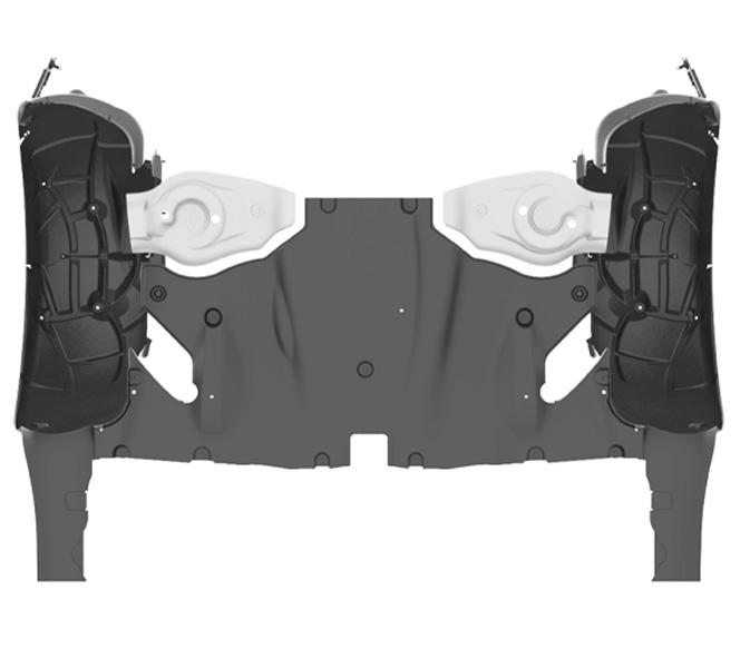
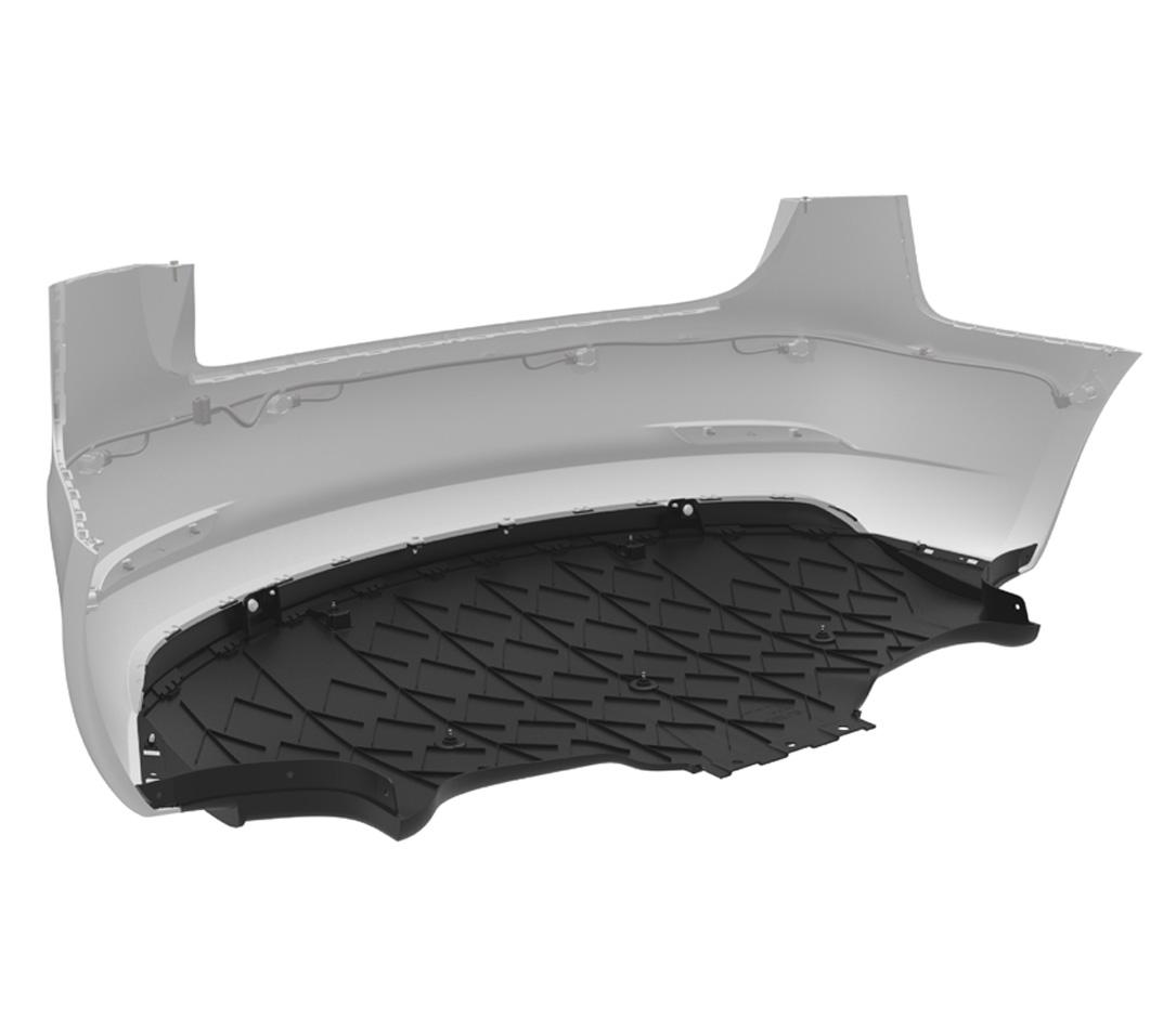
To reduce drag, the design of the Model 3 underbody uses molded plastic paneling that prevents air turbulence. Front to rear, the system begins at the front bumper fascia. Air for cooling and ventilation flows through the grill, which has active shutters to manage mass flow. Air then flows beneath the lower valence, which is attached to the front bumper fascia with a push-pull plastic rivet clips. The front aero shield covers the front subframe and the front valence. The rear aero shield covers the rear subframe and HV Battery, while overlapping with the wheel arch liners. The mid aero shield is located between the HV Battery and the rear diffuser. The rear suspension covers attach to the control arms of the rear suspension. The rear diffuser is the last piece of the underbody aero system. It attaches to the mid aero shield, the trunk load floor, and the rear lower bumper fascia. It cannot be removed from Model 3 without first removing the rear bumper fascia due to the use of buckle snaps.
 |
|---|
| Overview |
 |
|---|
| Front Aero Shield |
 |
|---|
| Mid Aero Shield |
 |
|---|
| Rear Aero Shield |
 |
|---|
| Rear Diffuser |
Exterior Mirrorslink
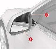
Model 3 has adjustable side mirrors with different features depending on the package. Base mirror packages are simple adjustable mirrors with manual folding. Premium mirrors have a heating system to prevent moisture obstruction, dimming, auto tilt, position memory, and power folding. Model 3 vehicles built between February 10th and August 23rd 2020 do no have dimming functionality installed. On August 24th 2020, auto-dimming sideview mirrors were re-introduced to Model 3.
 |
|---|
| 1. Mirror Skullcap 2. Mirror |
| Side-view Mirror |
Mirror Dimminglink
The Model 3 will dim mirrors to 47% when the following conditions are present:
-
Sun is down.
-
Headlights are on.
-
Drive gear (DI_gear) is D or N.
The solar elevation angle is calculated by the UI.
The rest of logic is implemented by the left vehicle controller (VCLEFT) and right vehicle controller (VCRIGHT) which control the mirrors.
VCLEFT controls the left mirror and VCRIGHT controls the right and rear-view mirrors.
There is no CAN signal to output the actuated dimming duty.
In the harness schematics, the Mirror Dim is also referred to as EC which stands for Electrochromic.
Electrochromism is the phenomenon where the color or opacity of a material (in this case glass) changes when a voltage is applied.
Wiper Systemlink
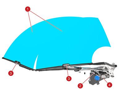
Model 3 has a variable speed windshield wiper system, a fluid pump, a sensor for low fluid detection, and a position detection sensor. These components enable Model 3 to clean and clear the windshield of reasonable debris and liquid. Actuation of the wiper system is requested by the front vehicle controller over a direct LIN connection, but is managed by integrated control electronics that are embedded into the gearbox cover of the wiper motor. The wiper speed and direction is controlled by varying the control signal and switching the polarity across the wiper motor respectively.
 |
|---|
| 1. Coverage area 2. Washer hose 3. Driver and Passenger windshield wiper assembly + washer nozzle 4. Washer fluid cap |
| Windshield Wiper System |
 |
|---|
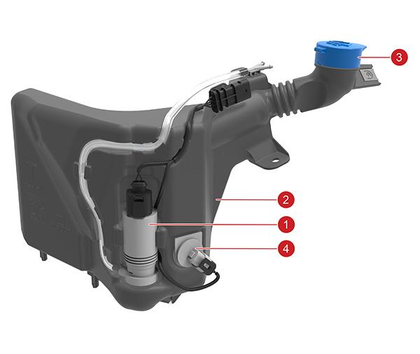
| 1. Washer Pump 2. Washer Tank 3. Washer fluid cap 4. Washer level sensor |
| Washer System |
If there is a blockage within the coverage area, the windshield wiper system will attempt to clear the blockage by performing break-off tests. The system may stop and move during the break-off tests in order to facilitate the clearing of any debris on the windshield. In the event that the blockage can not be cleared, the embedded electronics will stop the motor in order to prevent damage, and send a blocked signal to the front vehicle controller.
The tip wipe and wash cycles requests are controlled via a button located at the end of the left steering wheel stock. The wipe speed and on/off requests are controlled through the UI.
Heated Wiper Park Positionlink
Component Descriptionlink
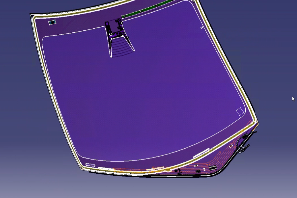
As of October 2021, Model 3 will have a heated wiper park position. The heater is located in the bottom of the windshield, below the cowl line. The heater is a copper wire embedded between the two panes of glass. These wires feed into a flat ribbon that converts to a round wire connector.
 |
|---|
| Above is the windshield with the wires of the heated wiper grid highlighted |
| Heated Wiper Park Position |
Theory of Operationlink
The heated wiper park position is triggered when the user chooses "Defrost" on the UI. If the outside ambient temperature is 50°F (10°C) or less the heater grid will turn on. The max temp of the heater grid is 158°F (70°C). The system will turn off the heater after 30 minutes if the user has not manually turned it off. The heated wiper grid communicates via VCFRONT.
Serviceabilitylink
The heated wiper grid has a 3 pin connector. The middle pin, Pin 2, is the ground wire, where Pin 1 is for the camera heater and Pin 3 is for the wiper heater park position grid. Voltage supplied to both the camera and wiper park position is 16.4V. Current for the heated wiper grid is 4.68A at room temp with resistance being 3.5Ohm.
Exterior Lightinglink
Overviewlink
The exterior lights on Model 3 are all LED components. Individual LEDs are not serviceable.
In late 2020, Global Headlamp was introduced for front and rear lights. Before that, regional lighting variants existed (SAE and ECE) to comply with market-specific regulations, with single country exceptions in lighting behaviors in Canada (SAE) and Iceland (ECE). SAE and ECE variants have different part numbers, while regional exceptions are administered via firmware. With Global Headlamp, regional differences can be recognized by software and the same hardware is used worldwide. Operation of the exterior lights is controlled by the three main vehicle controllers (Front, Left, Right). As with other low voltage components in Model 3, the exterior lights utilize electronic fuses incorporated into the vehicle controllers. The exterior lights respond to requests from:
- Light switch function of the touchscreen
- Ambient light information from the vehicle cameras and car computer
- Turn signal stalk
- Hazard switch
- Drive inverter (reverse light and brake light requests)
 |
|---|
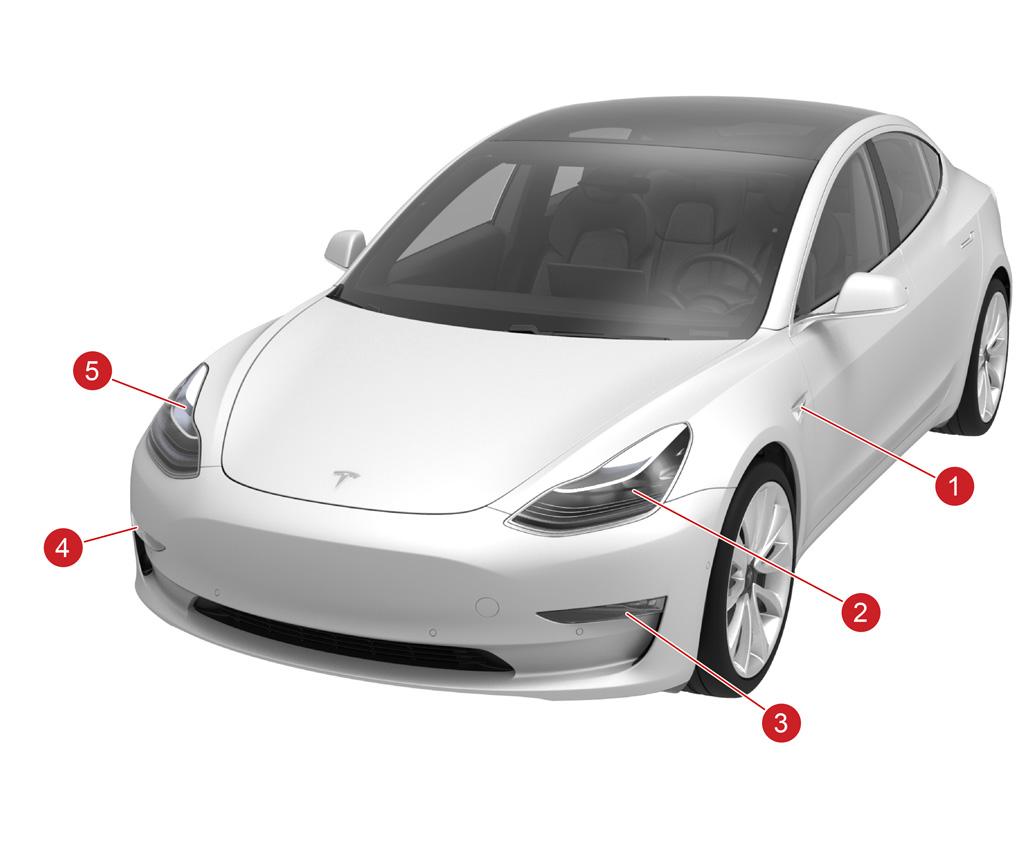
| 1. Side repeater camera assembly (left-hand) 2. Headlamp assembly (right-hand) 3. Fascia light assembly (left-hand) 4. Fascia light assembly (right-hand) 5. Headlamp assembly (left-hand) |
| Exterior Lighting Overview |
 |
|---|
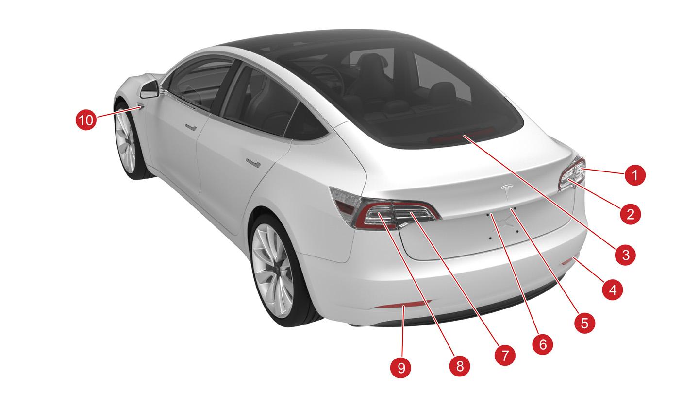
| 1. Body tail light 2. Liftgate tail light 3. Center high mounted stop light (CHMSL) 4. Reflex reflector 5. License plate light 6. License plate light 7. Lift gate tail light 8. Body tail light 9. Reflex reflector 10. Side repeater camera assembly |
| Exterior Lighting Overview |
Connectivity and Controllink
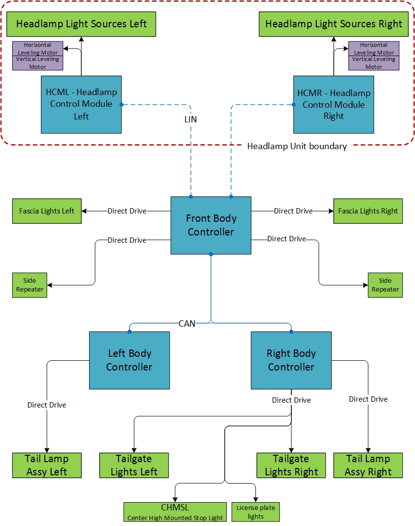
The exterior lighting system control is distributed between the vehicle controllers as depicted in the diagram below. The front headlights have their own ECU, the Headlamp Control Module (HCM), which is powering the individual LEDs inside the headlamp. The rear lights consist of the body and liftgate tail and stop lights as well as the license plate lights. They are managed by the left and right body controllers.
 |
|---|
| Headlamp Control Architecture |
The front body controller provides power and commands to the forward lighting. Forward lighting includes the headlights, front fascia lights, and side repeaters. The front headlights have their own ECU to command individual LEDs. The headlamp ECU communicates with the front body controller via LIN. The headlamp ECU is a serviceable component.
Lighting Component Descriptionslink
Exterior lights have two options, base or premium. Before late 2020, they were built to two different market specifications, SAE (typically North America) and ECE (Rest of World (RoW)). There are regional differences in lighting behaviors according to local governments. The variants are visually similar.
Headlamp Assemblylink
All headlamp assemblies are equipped with vertical leveling motors, used for beam alignment in the factory and in service. There are also variants with horizontal leveling motors as well, see the table below.
| Headlamp Type | Gateway config | Vertical leveling | Horizontal leveling |
|---|---|---|---|
| Global | GLOBAL | Yes | Yes |
| Regional SAE | PREMIUM | Yes | No |
| Regional ECE | PREMIUM | Yes | Yes |
ECE vehicles with coil suspension can perform automatic leveling of the headlights. Until late 2021, they were equipped with ride height sensors to evaluate the current vehicle pitch. The type of leveler can be checked in the gateway config under headlightLevelerType.
| Config value | Type |
|---|---|
| NONE | No leveling |
| GEN1 | Ride height sensors |
| VIRTUAL_PITCH_SENSOR | Virtual pitch algorithm |
Since then, the ride height sensors are replaced by a 'virtual pitch' algorithm that uses a combination of acceleration sensor signals by the RCM (restraints control module), GPS location and ride information by the drive unit. The difference between standard and premium headlamps is the intensity of the light emitted by the headlight. Cornering functionality does not exist for Model 3. Similar to the Model S and Model X, the Model 3 headlamps have Park / Signature lighting in SAE markets and Position / Daytime Running Light (DRL) lighting in ECE markets. The headlamp assembly attaches to the front carrier and fender with 4 bolts.
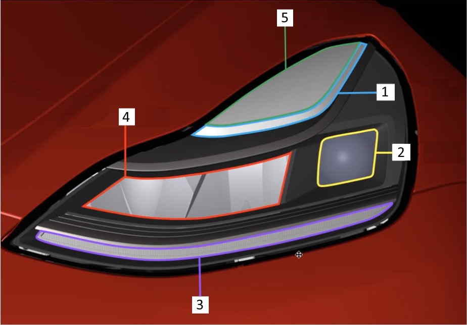 |
|---|
| 1. Park / Signature Light Guide (DRL Channel1) 2. Low Beam and High Beam Pixel Matrix (SSL100) 3. Turn indicator 4. Low Beam Pre-Field Reflector 5. Park / Signature Light (DRL Channel 2+3) |
| Front Headlamp Assembly, Global |
The SSL100 is a LED pixel matrix where the controller can activate each pixel individually and modify the light distribution according to the respective regional regulations and current lighting requirements. The low beam prefield is the homogenous light that forms most of the beam. The prefield reflector very specifically is the reflector for that light source. The reflector is a chrome piece of plastic that reflects the light from the LEDs to the correct directions.
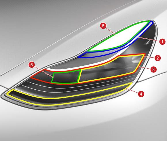 |
|---|
| 1. Park / Signature Light Guide 2. Premium Low Beam (Red) 3. Base Low Beam (Yellow) 4. Turn Indicator 5. High Beam 6. Park / Signature Diffuse |
| Front Headlamp Assembly, Regional |
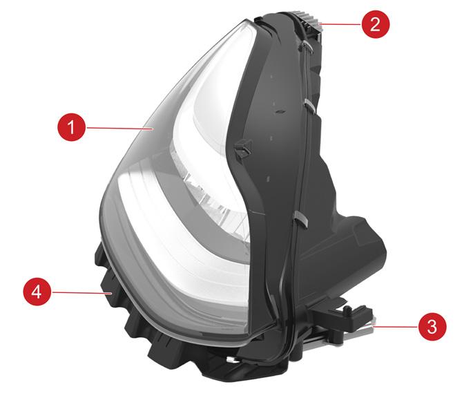 |
|---|
| 1. Headlight 2. Upper mounting bracket 3. Headlamp ECU 4. Lower mounting bracket |
| Headlamp Assembly, Components |
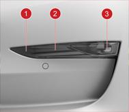
Front Fascia Lightlink
Premium models have a front fog light and an auxiliary park light. On vehicles sold in SAE markets, there is a side marker light. The front fascia light assembly must be replaced as an assembly. Individual components are not serviceable.
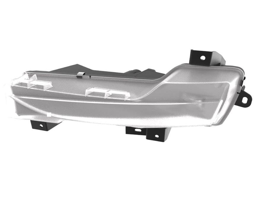 |
|---|
| Front Fascia Light Assembly |
 |
|---|
| 1. Side marker - SAE markets only 2. Auxiliary Park (fog light guide for ECE markets) 3. Fog light (fog lens ECE) |
| Front Fascia Light |
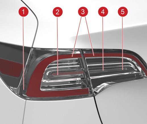
Tail Lightslink
Model 3 has the same style tail lights as the Model S and Model X, with lights on the body and liftgate. The charge port is hidden in the left-hand body light assembly. The brake lights and turn signals use the same LEDs as the tail lights, but the brightness is increased. The change in brightness is controlled by an LED Driver Module (LDM) mounted inside each light. This module changes the Pulse Width Modulation (PWM) signal to the LEDs to increase the brightness. The tail light assembly must be replaced as an assembly. Individual components are not serviceable.
 |
|---|
| 1. Side Marker (achieved by tail function) 2. Stop / Turn 3. Tail 4. Reverse 5. Non-functioning light blade |
| Tail Lights (SAE Markets) |
 |
|---|
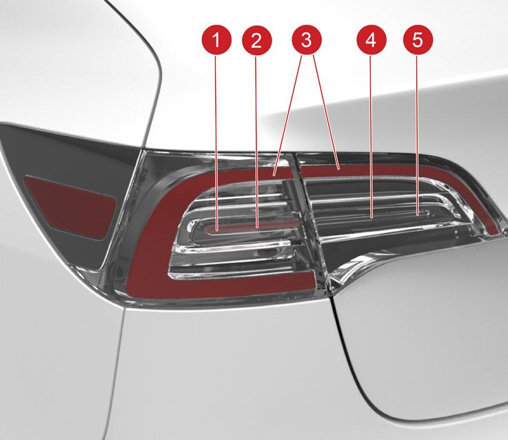
| 1. Turn 2. Stop 3. Tail 4. ReverseNote: Left-hand drive vehicles only: on the left-hand side, the reverse light is non-functioning and the rear fog light is present; on the right-hand side it is reversed. 5. Rear FogNote: Right-hand drive vehicles only: on the left-hand side, the rear fog light is non-functioning and the reverse light is present; on the right-hand side it is reversed. |
| Tail Lights (ECE Markets) |
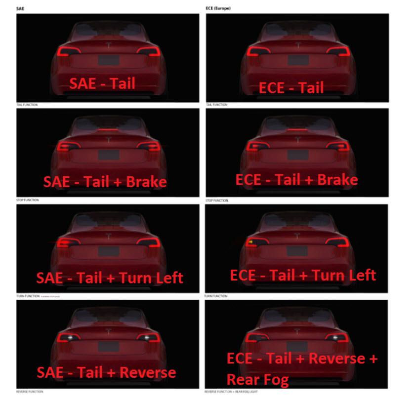 |
|---|
| Lighting behavior in SAE and ECE markets |
Side Repeater Assemblylink
The Model 3 side repeaters have an integrated camera for Autopilot functions. The LED indicator runs in the direction of travel above the camera, highlighted in the figure below. The side repeater assembly must be replaced as an assembly. Individual components (LED, Camera) are not serviceable.
 |
|---|
| 1. Side Repeater Indicator |
| Side Repeater |
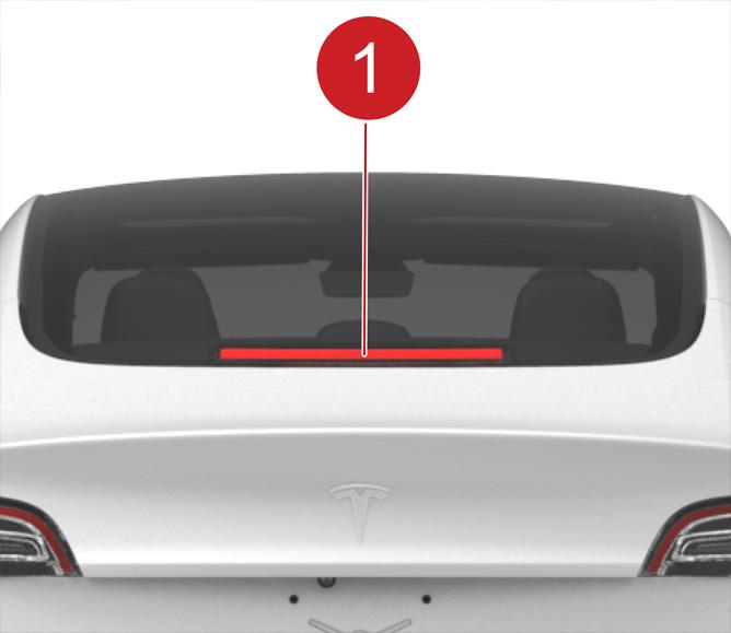
Center High Mounted Stop Light (CHMSL)link
The center high mounted stop light is part of the rear shelf, above the trunk, in the interior of Model 3. The assembly must be replaced as an assembly. Individual components (LEDs) are not serviceable.
 |
|---|
| Center High Mounted Stop Light |
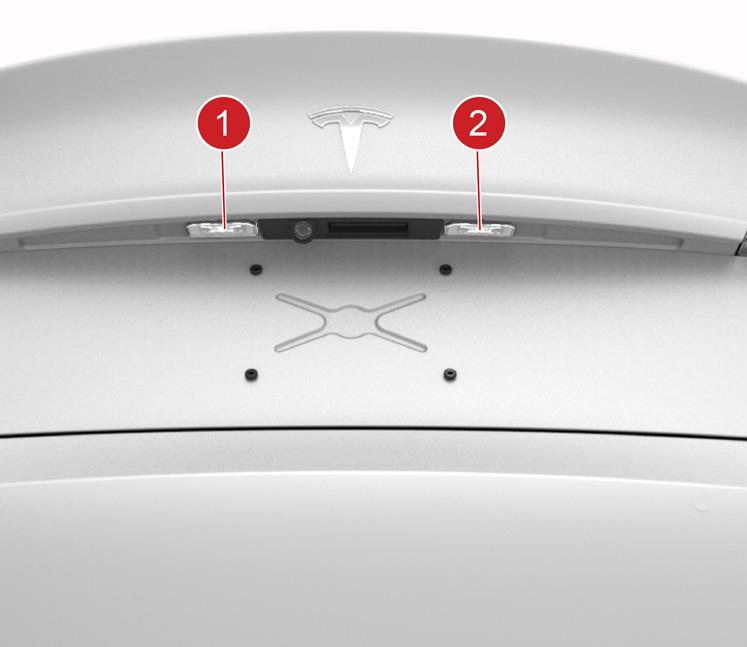
License Plate Lightlink
The two license plate lights are mounted on the lower edge of the liftgate, controlled by the right hand vehicle controller. Each light is LED and serviceable only as a unit.
 |
|---|
| 1. License Plate Light (left-hand) 2. License Plate Light (right-hand) |
| License Plate Light |
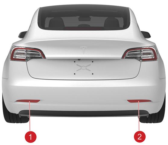
Reflex Reflectorslink
Reflex reflectors are mounted in the lower portion of the rear bumper. They reflect light to make approaching drivers aware of the vehicle’s presence without the use of vehicle power.
 |
|---|
| Reflex Reflectors |
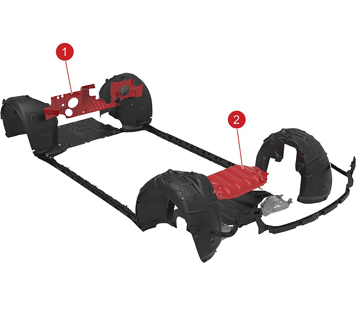
Noise, Vibration, and Harshness (NVH)link
Model 3 has front and rear motor noise absorbers. The front noise absorber is located between the instrument panel and the motor, and the rear noise absorber is located between the rear seats and the rear motor. Cutouts on the front noise absorber facilitate the installation of items like the HVAC module, front electrical system, the steering column, and other components of the instrument panel.
 |
|---|
| 1. Front motor noise absorber 2. Rear motor noise absorber |
| Noise Absorbers |
Wheel Linerslink
There are four wheel liners in Model 3. These help protect the vehicle against damage from rocks, dirt, salt, road debris, and weather elements. Wheel liners are snapped into place using push-pull rivets which attach the wheel liners to the body-in-white, front and rear fascias, front and mid aero shields, and base rocker covers. Removal of any one wheel liner requires the removal of more than ten push-pull rivets.