Drive Unitslink
Last updated: May 29, 2024
Overviewlink
Acronymslink
| Acronym | Term |
|---|---|
| DI (F/R) | Drive Inverter (Front/Rear); Also used for Drive Interface |
| DIG | Drive Interface Gateway |
| DSP | Digital Signal Processor |
| DU (F/R) | Drive Unit (Front/Rear) |
| EEPROM | Electrically erasable programmable read-only memory |
| MOSFET | Metal-oxide-semiconductor field-effect transistor |
| OPC | Oil Pump Controller |
| PCBA | Printed Circuit Board Assembly |
| PM (F/R/REL/RER) | Pedal Monitor (Front/Rear); Also used for Permanent Magnet |
| 2PO | Two Phase Open |
General Informationlink
Danger
Obey all high voltage safety requirements anytime the drive unit is part of a vehicle repair. The drive unit contains 550uF of internal capacitance, enough to be lethal if the internal discharge functions are not working properly. Always use a multimeter to confirm that dangerous voltage is not present on the DC input connector of the drive inverter.
The drive unit contains a motor, gearbox, and drive inverter. The component parts of the assembly are highly integrated to reduce system complexity and improve reliability.
The drive unit takes electrical energy from the battery and converts it into mechanical torque, which is transferred to the wheels.
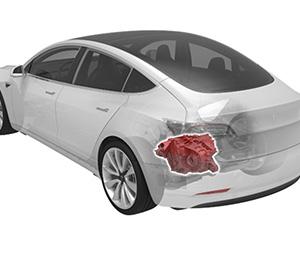
The rear drive unit is located between the rear wheels, underneath the trunk. The half-shafts connect the wheels to the drive unit. The rear drive unit assembly is mounted to the rear sub-frame with three mounts:
- A rear mount, integrated into the gearbox case
- A right mount, integrated into the motor housing,
- A left mount, bolted on the gearbox housing above the drive inverter.
 |
|---|
| Rear Drive Unit - Location |
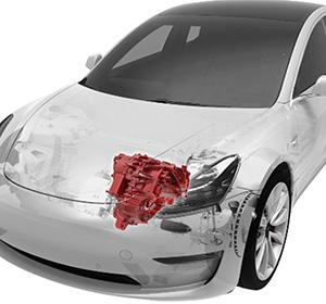
The front drive unit assembly is mounted to the front subframe with three mounts:
- A front mount, integrated into the gearbox case, and connected via the front subframe
- A right mount, integrated into the motor housing
- A left mount, bolted on the gearbox housing above the drive inverter.
 |
|---|
| Front Drive Unit - Location |
For All-Wheel Drive (AWD) vehicle configuration, each drive unit gives motion to the wheels in the respective axle. The two drive units are not mechanically connected to each other.
The drive units connect to the vehicle in six ways:
- High Voltage (HV) Harness
- Low Voltage (LV) Harness
- Half-shafts
- Coolant Hoses
- Mounts (x3)
- Ground strap
The drive unit(s) are mechanically and electrically connected to the vehicle.
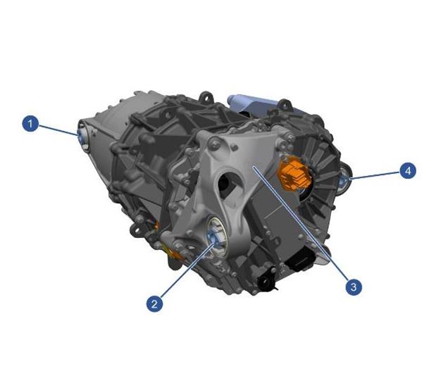
 |
|---|
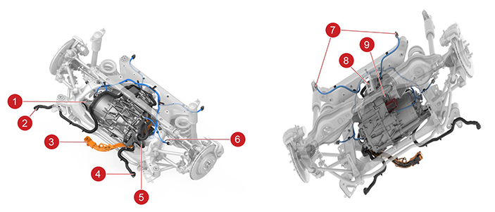
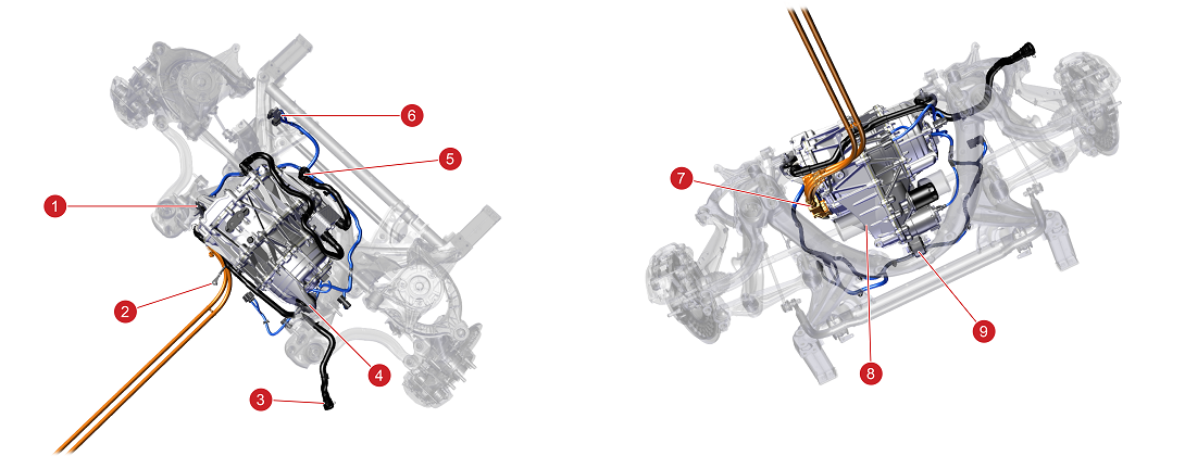
| 1. Right Drive Unit Mount to Subframe 2. Rear Subframe Coolant Outlet 3. HV Battery Connector for Rear drive unit 4. Rear Subframe Coolant Inlet 5. Left Drive Unit Mount to Subframe 6. Drive Unit Chassis ground point 7. Rear Subframe Low Voltage Harness Connectors (to Body) 8. Rear Drive Unit Mount to Subframe 9. Drive Unit Torque Output |
| Rear Drive Unit - Mounting and Connections |
 |
|---|
| 1. Left Drive Unit Mount to Subframe 2. Drive Unit Chassis ground point 3. Front Subframe Coolant Inlet 4. Right Drive Unit Mount to Subframe 5. Front Subframe Coolant Outlet 6. Front Subframe Low Voltage Harness Connector 7. HV Connector to Front Drive Unit 8. Drive Unit Torque Output 9. Front Drive Unit Mount to Subframe |
| Front Drive Unit - Mounting and Connections |
 |
|---|
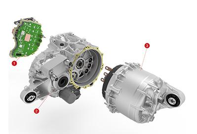
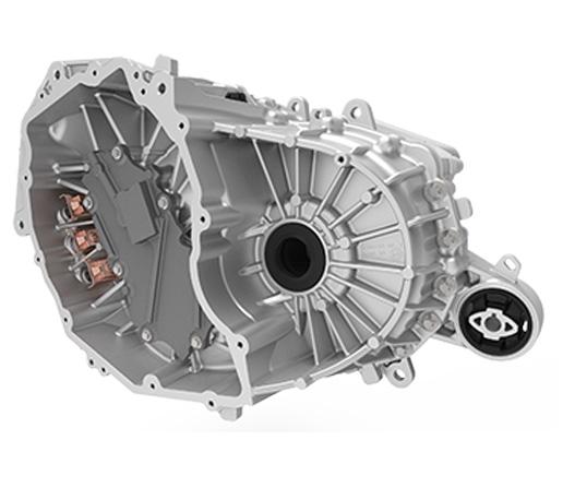
| 1. Drive Inverter 2. Gearbox 3. Motor |
| Rear Drive Unit(3DU) - Exploded View - Main Components |
 |
|---|
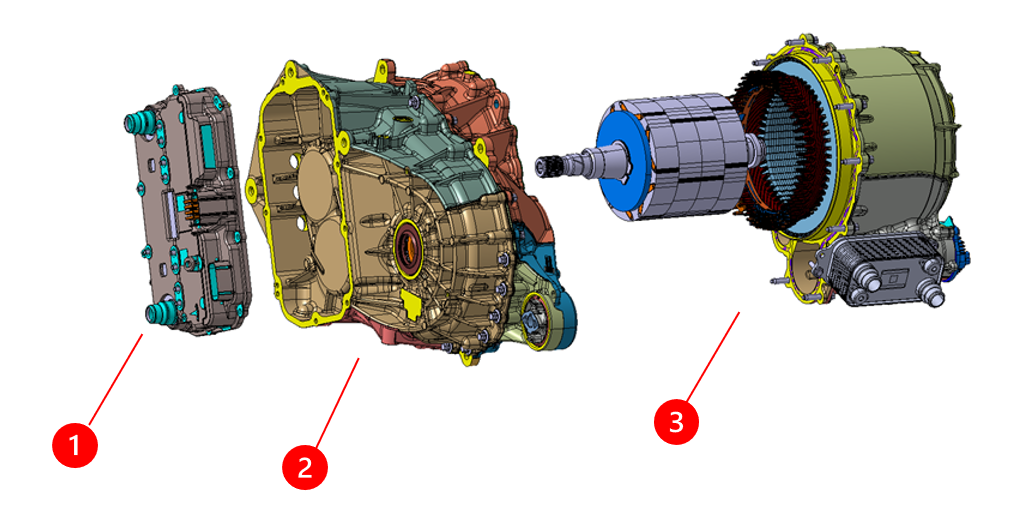
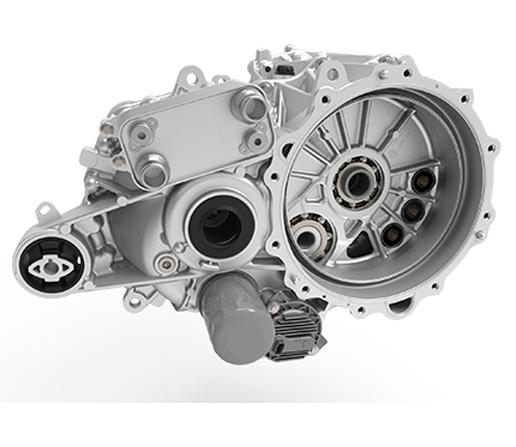
| 1. Drive Inverter 2. Gearbox 3. Motor |
| Rear Drive Unit(4DU) - Exploded View - Main Components |
 |
|---|
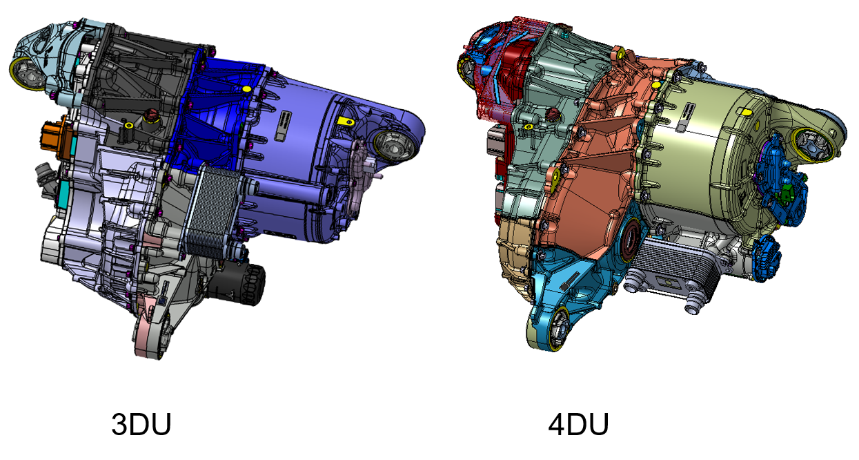
| Visual Difference Between 3DU and 4DU |
 |
|---|
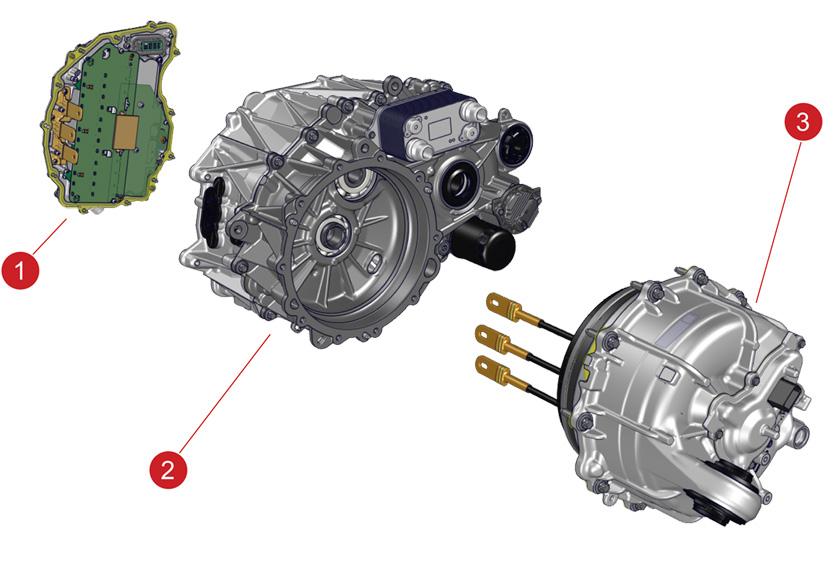
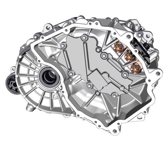
| 1. Drive Inverter 2. Gearbox 3. Motor |
| Front Drive Unit - Exploded View - Main Components |
Drive Unit Mountslink
 |
|---|
| 1. Right Mount Bushing 2. Left Mount Bushing 3. Left Mount 4. Rear Mount Bushing |
| Rear Drive Unit Mounts |
Note
Rear drive unit shown, front drive unit is similar.
Coolant Hose Connectionslink
 |
|---|
| 1. Drive Inverter Coolant Outlet 2. Rear Subframe Coolant Inlet 3. Drive Inverter Coolant Inlet 4. Heat Exchanger 5. Heat Exchanger Inlet 6. Rear Subframe Coolant Outlet 7. Heat Exchanger Outlet |
| Rear Drive Unit Coolant Hose Connections |
Note
Rear drive unit shown, front drive unit is similar.
High and Low Voltage Connectionslink
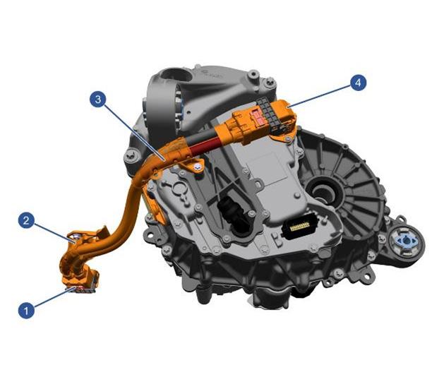 |
|---|
| 1. HV Battery Connector 2. Drive Inverter DC Voltage Bracket 3. Drive Inverter DC Voltage Bracket 4. Drive Unit Connector |
| High Voltage Connections |
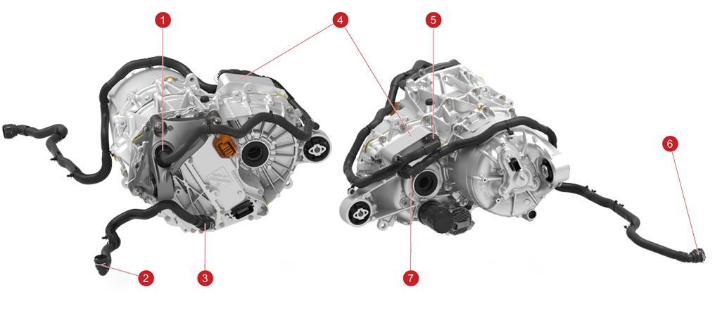
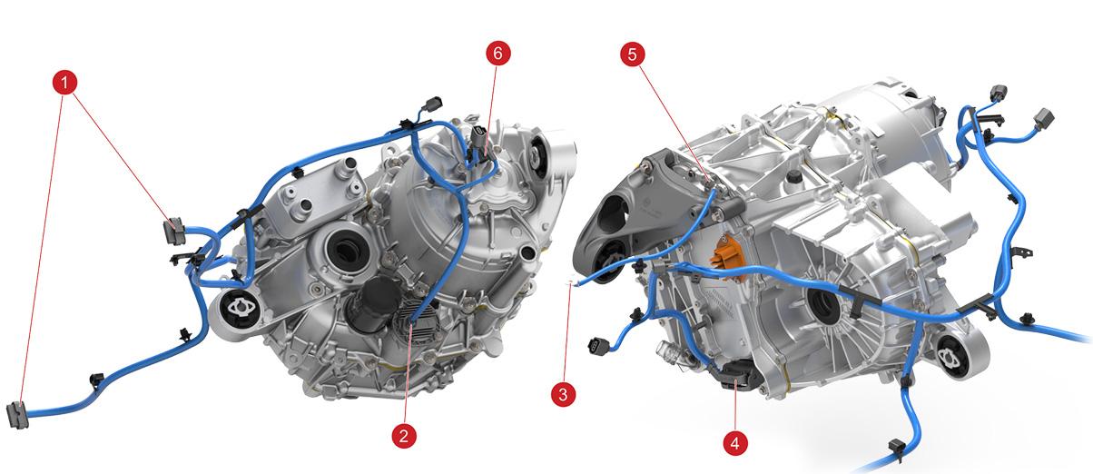 |
|---|
| 1. Rear Subframe Harness Connectors to Body 2. Oil Pump Connector 3. Ground to Chassis 4. Drive Inverter Logic Connector 5. Ground Attachment 6. Resolver / Stator Thermistor Connector |
| Rear Drive Unit Low Voltage Harness Connections |
Note
Rear drive unit shown, front drive unit identical.
Drive Inverterlink
Overviewlink
The drive inverter converts the Direct Current (DC) from the battery pack into three Alternating Current (AC) phases in the stator. The current waveforms are 120° out of phase with each other and create a rotating magnetic field in the stator.
For an induction motor, the stator field induces current in the rotor. The induced rotor current creates a second magnetic field that opposes the stator field, producing motor torque.
For a permanent magnet motor, the permanent magnets inside the motor have a permanent magnetic field. The interaction of this permanent field with the stator's rotating magnetic field produces a motor torque. The speed of the motor depends on the frequency of the AC supplied by the drive inverter. The torque of the motor depends on the amplitude of the AC. In a permanent magnet motor, the torque will also depend on the electrical angle difference between stator and permanent magnet, magnetic fields.
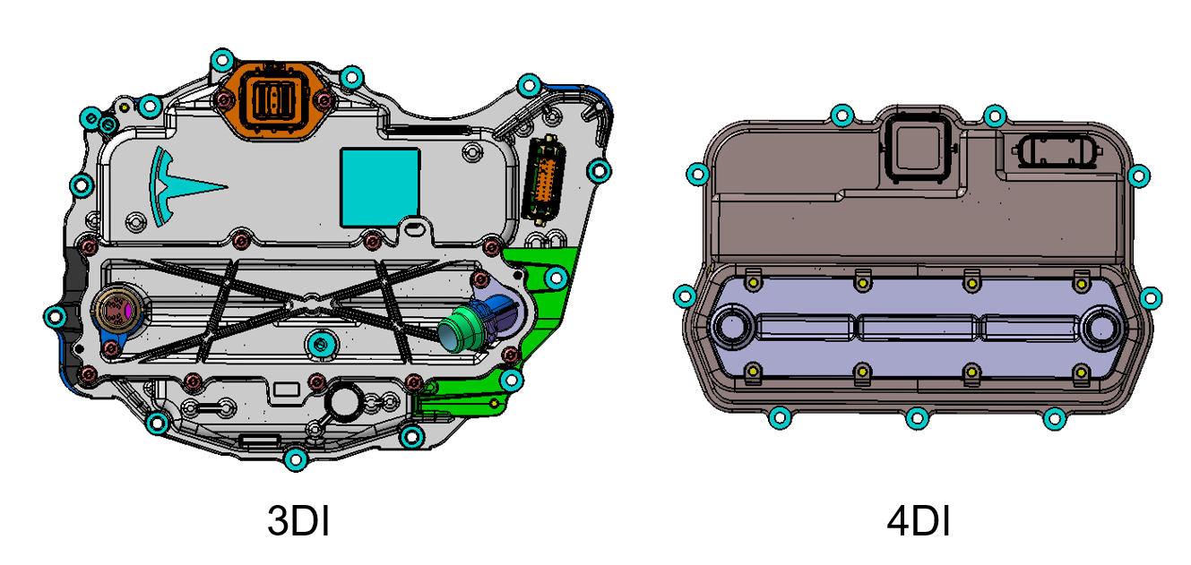
The introduction of 4DU for the Performance package includes a 4th generation drive inverter (4DI). The major differences between 3DI and 4DI are:
- Semi-custom gate drive IC: STGAP4S
- Planar transformers with ferrite for gate drive power supplies
- Secondary processor for deploying two-phase open or removing three-phase shorts if main processor is unpowered or unavailable
 |
|---|
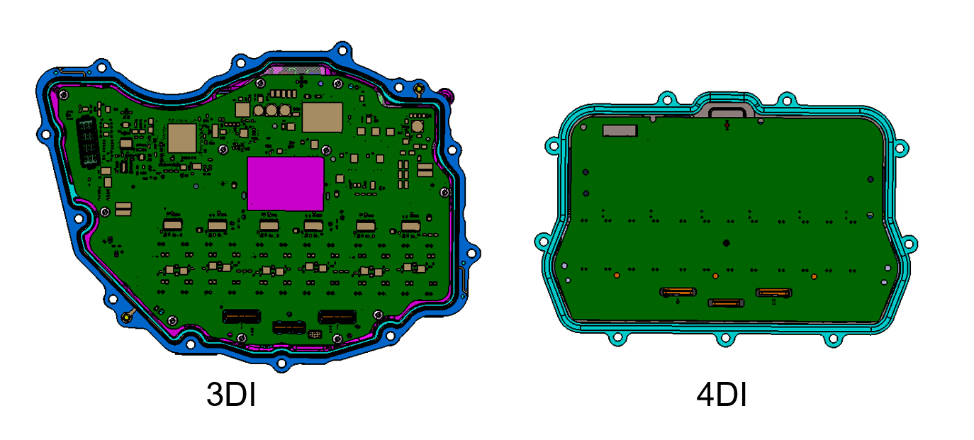 |
| Visual Difference Between 3DI and 4DI |
 |
|---|
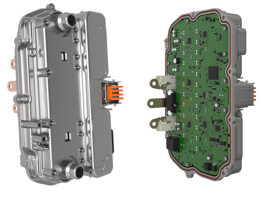
| 4DI Rear Drive Inverter |
 |
|---|
| 4DI Rear Drive Inverter |
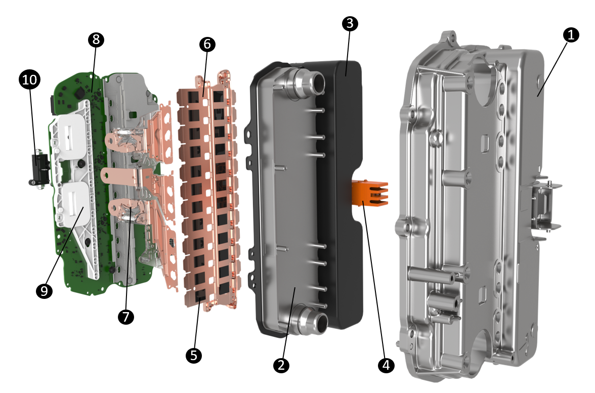
| 1. Inverter Case 2. Inverter Heatsink w integrated Coolant Ports 3. DC Link Capacitor 4. HV Header 5. Metal-oxide-semiconductor field-effect transistor (MOSFET) 6. Busbars 7. 3-Phase Bus Bars (connect inverter to stator) 8. Inverter PCBA 9. Current Sensors 10. Two Phase Open (2PO) Pyro |
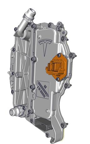
Front Drive Inverterlink
 |
|---|
| Front Drive Inverter |
Each drive inverter translates the torque commands from the external system torque processor, named "external drive interface", which is located in the right vehicle controller (VCRIGHT), into alternating currents that are applied to the motor in order to generate the correct speed, torque, and direction of rotation to move the vehicle. The drive inverter is a bi-directional system, converting battery current to motor current and vice-versa. Regenerative braking is achieved using the drive inverter as rectifier to transfer current from the motor to the battery.
The drive inverter PCBA has a dual core digital signal processor (DSP). The main core controls the motor, monitors the health of the drive system, and processes driver requests. The second core, referred to as the Propulsion Monitor, is a processor that can stop torque generation if the motor currents, speed, or accelerator pedal conditions indicate that the main processor is not operating correctly. The two cores can be programmed over the CAN interface and communicate to each other over shared memory. An Electrically Erasable Programmable Read-Only Memory (EEPROM) stores the part and serial numbers of the PCBA, inverter, and drive unit allowing pedigree tracking. Gate drive circuit converts the switching signals generated by the main DSP core into signals that can drive the power semiconductors. The power semiconductors use these signals and high voltage battery power to generate the appropriate current in the three stator phases.
Operationlink
The drive inverter monitors the temperatures of the motor and power electronics. It sends cooling requests for the motor, gearbox, and inverter electronics to the thermal controller. There is no direct control over the coolant flow or fan speeds from the drive inverter; the thermal controller manages the system to optimize for range and efficiency. If thermal limits are exceeded, the drive inverter limits motor torque until the temperatures are back within nominal operating range.
The drive inverter has 24 power semiconductor devices (Tpaks) for 840A inverters, and 18 power semiconductor devices (Tpaks) for 630A inverters.
Busbars connect these to battery+, battery-, and the three phases.
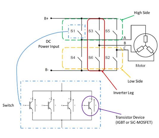
The drive inverter consists of 6 switches, each one built from 4 semiconductor devices in parallel for 840A inverters, and 3 semiconductor devices in parallel for 630A inverters. High side switches are between battery positive and phase out while low side switches are between phase out and battery negative. Each phase of the inverter has one high side switch and one low side switch. The inverter generates three phase AC current by activating and deactivating the six switches as needed to shape the current routed through the stator.
 |
|---|
| Drive Inverter, Simplified Circuit Diagram |
 |
|---|
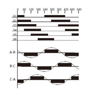
| Creating 3-Phase AC |
Communicationlink
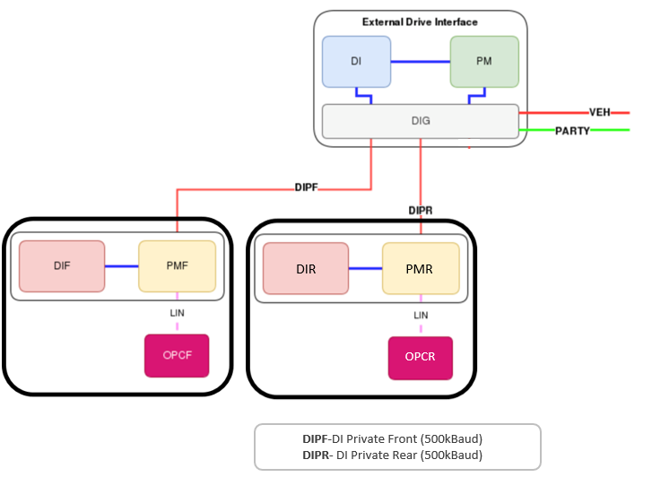
The communication architecture consists of an external drive interface, which is located on the right vehicle controller (VCRIGHT). The external drive interface gets inputs from the gear selector, the accelerator pedal, and the brakes in order to define the operating condition and sends appropriate torque requests to all unit inverters via independent private CAN buses. The external drive interface consists of 3 controllers:
- drive interface
- pedal monitor
- drive interface gateway (DIG)
- DIG handles the communication between the private CAN buses and the Vehicle and Party CAN.
The external drive interface calculates the required torque split for both front and rear motors, along with cruise control and traction control. The unit inverters do not have direct accelerator inputs, so they rely on private CAN bus communication in order to report internal failures to the Vehicle and Party CAN buses. Errors are identified when alerts are received. Alerts are capable of communicating information such as the lack of torque commands from the external drive interface, or that the external drive interface is missing in action (MIA).
 |
|---|
| Drive Inverter CAN Communication Architecture |
Fault Protectionlink
The inverter fault monitoring uses a range of sensors to protect the inverter and motor hardware in order to provide the most desirable outcome for the driver.
Switch-Off Path Test (SOPT)link
The switch-off path test is run on every Drive Unit power up to test the functionality of the system responsible for safely shutting down the unit torque production. This test ensures that the shutdown process is executed correctly and reliably, preventing any unintended operation or potential damage while in drive. A non-torque-producing current is sent from the Drive Inverter (DIx) and subsequently shut down by the Propulsion Monitor (PMx) to validate proper operation. The test is twofold, ensuring that drive unit gate drive circuit is healthy and can generate current and that Propulsion Monitor has full authority over the Drive Inverter.
Serviceabilitylink
Alerts
The following alerts will be present during a drive unit power up if the SOPT test fails. Persistent SOPT are usually indicative of gate drive circuit failures or other internal faults like shorts. Looking at alert payload is not required.
DIX_a024_selfTest- SOPT test failure reported by the DIPMX_a033_selfTest- SOPT test failure reported by the PM
Safe Statelink
A motor inverter safe state is a predetermined and controlled mode that is engaged when the drive inverter encounters abnormal or hazardous operating condition. It actuates the low side and high side switches (MOSFETs) to the best possible outcome to prevent propagating failures. Any torque requests are overridden during Safe State.
| Safe State Type | Low Side Switch State | High Side Switch State | Safe State Application Triggers |
|---|---|---|---|
| None | Normal | Normal | No safe state applied. Normal Drive Inverter operation |
| All-Off | Open | Open | GDIC Fault, Phase Overcurrent, Desaturation, Uncontrolled Regen |
| Low Side 3 Phase Short (LS-3PS) | Closed | Open | Bus Overvoltage, Loss of LV, Pedal Monitor Torque Intervention. May also be applied per the current observer's recommendation |
| High Side 3 Phase Short (HS- 3PS) | Open | Closed | Not automatically applied but can be applied as a result of the current observer's recommendation. |
Current Observerlink
Current observer is triggered following a Safe State application (or any change in Safe State thereafter). The current observer will recommend a new Safe State based on its observation.
If the current observer does not detect any hardware issues, it will recommend the Safe State to return to None, and a retry is attempted.
MOSFET Desaturationlink
Saturation voltage is the voltage drop across the MOSFET when current is flowing through. During normal operation, the resistance loses are dissipated in the form of heat through the inverter heatsink and into the coolant loop. If the voltage drop across the MOSFET increases beyond the allowed threshold, this is known as desaturation. This typically occurs in the event of a short circuit, where unexpectedly high currents are flowing through the MOSFET. If not controlled quickly, the MOSFET can overheat and fail.
A desaturation fault detection provides protection against short circuit events by turning off the MOSFET when the saturation voltage exceeds maximum limit.
Two-Phase Open (2PO)link
Overviewlink
2024 Model 3 uses one permanent magnet drive unit either on the rear. When the wheels spin, the magnets generate a voltage inside the motor. This voltage needs to be controlled even if the torque command is zero. The drive inverter stops switching (hibernates) during normal operation only if the drive torque command is zero, the waste heat command is zero, and the speed is low enough that the voltage in the motor will not induce uncontrollable deceleration. This voltage needs to be controlled even if the drive unit is in a fault state until the vehicle comes to a full stop. For this reason, in case of semiconductor (TPAK) failure, such as single or double phase shorts, the inverter deploys the two-phase open pyro to physically break the connection on two of the three phases. This disconnects the inverter and high voltage battery from the motor and protects against high voltage battery shorts and high voltage battery pyro deployment. The inverter then checks that the two-phase open deployed successfully and the vehicle is able to continue driving on the remaining drive units.
For cases where DIx chip is unavailable or unable to deploy the pyro, the Secondary Disconnect Controller (SDC) ECU is introduced as a backup actuation method for the pyro. See the Secondary Disconnect Controller (SDC) section below.
Operationlink
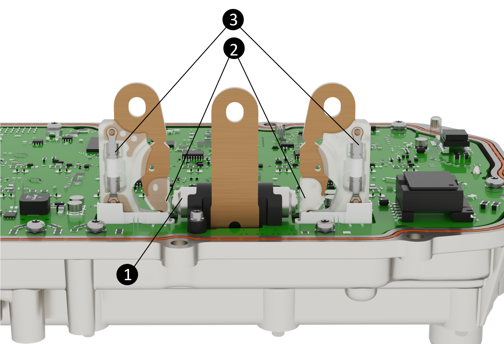 |
|---|
| 1. Two-phase open pyro device 2. Phase lug breakaway points 3. Fuses |
| Two Phase Disconnect Pyro Device |
Secondary Disconnect Controller (SDC)link
Specificationslink
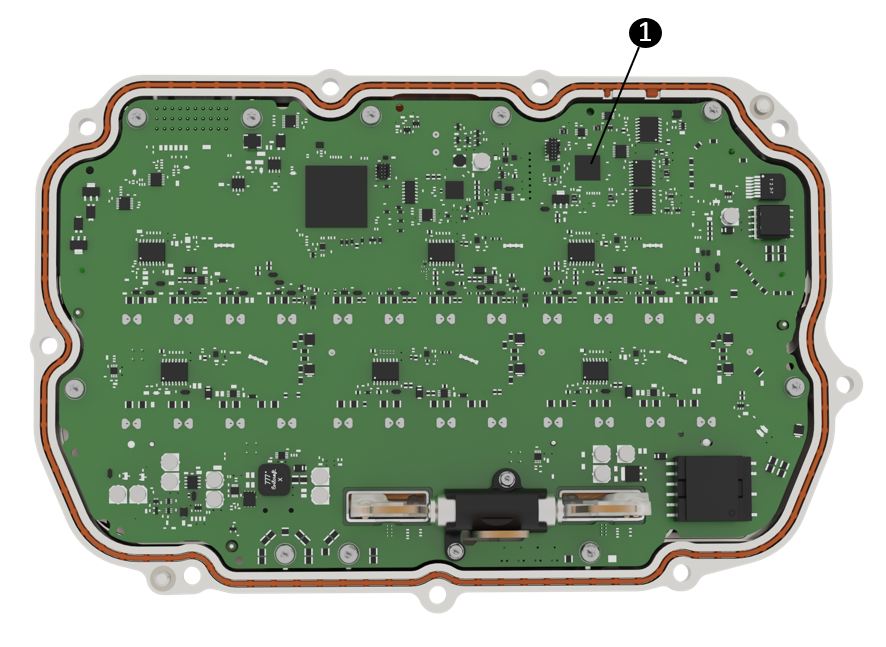 |
|---|
| 1. Secondary Disconnect Controller |
Operationlink
Secondary Disconnect Controller (SDC) is a fallback controller responsible for actuation of the two-phase open (2PO) pyrotechnic fuse inside the drive inverter when the DI chip is unavailable or unable to do so. Some conditions may include:
- Unintended reset of the DI.
- Abrupt loss of low voltage power to DI.
- Uncontrolled regenerative braking torque caused by towing abuse (high speed wheels on the ground towing) with DIx chip unpowered.
- Other DI chip or board level failures.
SDC can trigger the 2PO pyro to prevent further propagation of the fault and damage to upstream components in the HV circuit. It is powered by three redundant power sources supplying 5V for reliable operation under various fault conditions:
- Low voltage - from the vehicle low voltage circuit.
- DC high voltage - from the high voltage battery.
- Rectified back electromotive force (emf) DC high voltage - energy produced by the motor while vehicle is coasting.
The SDC cannot be repaired or replaced independent of the drive inverter as it is part of the drive inverter PCBA.
Serviceabilitylink
The following alerts can be used to quickly identify Drive Inverter hardware faults:
Note
For the alerts below, x may be F or R depending on whether the front or rear drive unit is being diagnosed.
DIx_a156_currentObserver-This alert is triggered when the current observer is executed. The payload can tell:a156_initialSafeState- Initial Safe State at time of observation.a156_safeStateRecommend- Recommended Safe State based on observation.a156_observation- The observed hardware fault.
DIx_a244_mechSafeStateApplied- Triggered when 2PO pyro is triggered (will not trigger again).DIx_a244_postShortTestFailed- The 2PO pyro has triggered if = 1.DIx_a015_mechSafeStateAnomalywill be present on every power up if the 2PO pyro was triggered.
DIx_a00x_hwPhaseXgateDrive- Indicates whether there was a desaturation event detected on high side (a00X_desat_H) or low side (a00X_desat_L).
Note
The shorted MOSFET is usually on the opposite side of the MOSFET reporting desaturation.
SDCx_a006_pyroTriggered- SDC triggered the 2PO pyro. This will only show at time or when triggered.SDCx_a007_faultCurrentsDetected- Abnormal currents are detected but does not necessarily trigger 2PO pyro. If DI is also MIA, it will trigger pyro.
Limp Modelink
Similar to drive inverter fault protection, Limp Mode is intended to protect the vehicle hardware when a fault is detected. The vehicle's performance is intentionally constrained to a basic level, allowing the driver to navigate to a safe location for inspection or repair. This mode can involve reducing power output, limiting speed and/or acceleration, and displaying warning indicators and speed limit to alert the driver of the problem. This can be limited to an individual drive unit (unit limp) or across a vehicle powertrain system (system limp).
If the system is confirmed to have fully recovered, the restrictions imposed during limp mode will be lifted, allowing the vehicle performance to return to normal.
Serviceabilitylink
Note
For the alerts below, x may be F or R depending on whether the front or rear drive unit is being diagnosed.
DIx_a062_systemLimpMode- Indicates a system limp mode, meaning there was a fault detected somewhere in the powertrain system.DIx_a062_limpReason- Shows which condition caused the system limp.DIx_a126_limpMode- Indicates a unit limp mode, meaning there was a fault detected by the unit.DIx_a126_limpReason- Shows which condition caused the unit limp.
Note
There are limp reasons that may require further investigation. Do not indicate a fault with the unit reporting it. Some examples are:
DI_LIMP_TRQCMD_VALIDITY_UNKNOWN- Indicates a missing or invalid torque command from the Drive Interface.DI_LIMP_PMREQUEST- Indicates limp mode was requested by the PM/PMx node. Review of the PM/PMx node alerts will show the cause for the limp request.
HVIL Over CANlink
The drive inverters report their HVIL status to the high voltage processor (HVP) via CAN, this communication method is referred to as HVIL over CAN. For redundancy, each drive unit has the pedal monitor (PM) and drive inverter (DI) report its HVIL status individually over independent private CAN buses to the external drive interface (located externally in the right vehicle controller).
The drive interface aggregates these HVIL statuses from each DI and PM and sends a single HVIL status signal to the HVP indicating whether HVIL at DI is closed, open, or none (missing).
This setup makes the HVP agnostic to the DI configuration of the vehicle (1 or 2 drive inverters), as the external drive interface manages it and sets the primary inverter HVIL status accordingly. The external drive interface sends the aggregated HVIL statuses to the high voltage battery management system (HVBMS) and HVP.
Waste Heat Modelink
The 2024+ Model 3 does not have an external high voltage coolant heater. All the heat that the High Voltage (HV) battery needs is provided by the powertrain, even when the vehicle is parked. Both front and rear drive units contribute to waste heat mode. Under cold soak conditions, the front vehicle controller (VCFRONT) sends a request to the drive inverter(s) to produce the necessary power that is required to heat the coolant and therefore HV battery cells. Current is used to heat the stator without changing the torque/speed output, which will heat the transmission fluid being pumped and heat transferred to the coolant being pumped thought the heat exchanger.
- If the vehicle is being driven, the motor control strategy changes to produce excess powertrain losses in order to provide heat to the HV battery.
- If the vehicle is parked in the cold and the HV battery needs to be heated up, the drive inverter provides the appropriate current to the motor to produce heat with zero torque/speed change.
Regenerative Brakinglink
Regeneration operates on the principle that the electric motor can also act as an electrical generator. This places a load on the motor, which in turn provides an additional braking effect.
The amount of regen torque generated is dependent on vehicle speed, battery state of charge, the accelerator pedal position, and user specified regen settings (setting is only available in China). The brake pedal provides maximum available regen torque when fully released, then proportionally less as the pedal is depressed. The motor delivers zero regen torque when the accelerator pedal reaches its neutral torque position, which moves depending on driving and vehicle conditions.
Note
A failure of the ABS or electronic stability program (ESP) system disables regenerative braking. A notification is displayed on the touchscreen. Regen may also be reduced or disabled when the tires may be traction limited, such as in cold weather or during traction control events. Regen is limited or disabled if battery state of charge (SOC) is too high.
The drive inverter converts this torque command into the appropriate 3-phase voltage and current waveforms to produce the commanded torque in the motor in the most efficient way. The torque command can be positive or negative. When the torque is used to slow the vehicle, energy is returned to the HV battery to store for later use.
The maximum regeneration braking profiles take both speed and corresponding drag into account to aim for a target total vehicle deceleration rate, not an energy recovery target. Regeneration braking profiles are tailored to everyday driving conditions, and typically provide higher deceleration rates at lower speeds.
If Apply Brakes When Regenerative Braking is Limited is enabled in the UI, then the regen backfill feature is enabled. Regen backfill is meant to provide consistency in deceleration feel such that regen modulation when releasing the acceleration pedal has little to no variation regardless of conditions by utilizing the iBooster automatically. The primary reasons backfill is needed are high state of charge or cold temperatures of the battery.
Temperature Sensorslink
The drive inverter has 5 temperature sensors:
- 2 on heat sink between phases
- 1 on the heat sink near the fluid port closest to the logic connector
- 1 on the front of the PCBA near the DSP
- 1 on the back of the PCBA behind the active discharge resistors
Other temperatures such as the DC link capacitor and phase out busbar are calculated in real time by the main core of the DSP. If the inverter detects any of these temperatures exceeding expected values (if coolant flow is lost for example), it will limit its own power output to an operational level.
Drive Inverter Printed Circuit Board Assemblylink
The drive inverter logic board has:
- Private CAN bus.
- Dual core processor
- One for motor control
- One to monitor torque generation and stop it when needed
- High voltage supplied fault response
- Low side three-phase short
- 2 phase open pyro
- 2 phase current sensors
- The current of the 3rd phase is calculated measuring the other two.
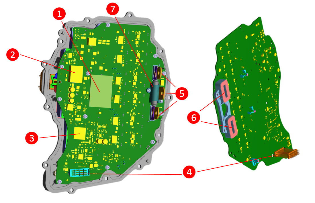 |
|---|
| 1. Active discharge resistor gap pad 2. Gate drive power supply 3. Dual core DSP 4. Logic connector pins 5. Three phase out busbars 6. Current Sensors 7. Two phase open pyro |
| Drive Inverter Printed Circuit Board (PCB) |
 |
|---|
| Pin | Name | Type (perspective of the inverter) | Notes | Current |
|---|---|---|---|---|
| Rear Inverter | ||||
| 1 | ||||
| 2 | CAN- | CAN -N | Private CAN(to VCRIGHT) | |
| 3 | Switched +12V | Power In | Switched +12V line to inverter | 3A Stall3A Steady |
| 4 | ||||
| 5 | ||||
| 6 | ||||
| 7 | Resolver Sine- | Analog In | Twisted pair with Resolver Sine +. Connects to back of motor (J2 on same device) | |
| 8 | Resolver Cosine+ | Analog In | Twisted pair with Resolver Cosine -. Connects to back of motor (J2 on same device) | |
| 9 | ||||
| 10 | Oil Pump Status | LIN | Connects to oil pump | |
| 11 | ||||
| 12 | CAN+ | CAN -P | Private CAN(to VCRIGHT) | |
| 13 | GND | Ground- | Main ground connection of inverter to chassis | |
| 14 | ||||
| 15 | ||||
| 16 | Resolver Excitation- | Analog Out | Twisted pair with Resolver Excitation +. Connects to back of motor (J2 on same device) | 100mA Steady |
| 17 | Resolver Sine+ | Analog In | Twisted pair with Resolver Sine-. Connects to back of motor (J2 on same device) | |
| 18 | ||||
| 19 | ||||
| 20 | ||||
| 21 | ||||
| 22 | Unswitched +12V | Power In | Power for active discharge control while inverter is off | 20mA Stall20mA Steady (contactors closed)100uA Steady (contactors open) |
| 23 | ||||
| 24 | ||||
| 25 | ||||
| 26 | Resolver Excitation+ | Analog Out | Twisted pair with Resolver Excitation - Connects to back of motor (J2 on same device) | |
| 27 | Resolver Cosine- | Analog In | Twisted pair with Resolver Cosine + Connects to back of motor (J2 on same device) | |
| 28 | ||||
| 29 | ||||
| 30 |
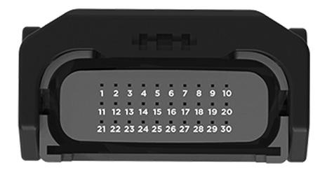
Note
All pins are gold plated and sized the same: 0.64x0.64FS. Harness-side Drive Inverter Connector
Related Vehicle Componentslink
 |
|---|
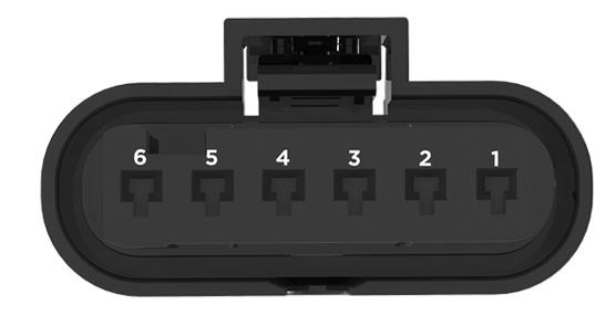
| Pin | Name | Type (device-defined, from the view of the Accelerator Pedal) | Notes |
|---|---|---|---|
| 1 | Accel_Ref2 | Power In | Sensor 2 |
| 2 | Accel_Sig2 | Analog Out | Sensor 2 |
| 3 | Accel_Rtn2 | Ground Return | Sensor 2 |
| 4 | Accel_Rtn1 | Ground Return | Sensor 1 |
| 5 | Accel_Sig1 | Analog Out | Sensor 1 |
| 6 | Accel_Ref1 | Power In | Sensor 1 |
Note
All pins are gold plated and sized the same: 1.2x0.6FS. Accelerator Pedal Connector (Harness-Side Connector)
Gearboxlink
Overviewlink
The drive unit features a single speed gear reduction gearbox, located between the motor and the drive inverter. The gearbox uses a layshaft arrangement with two stage gear reduction.
There is no mechanical linkage between the gear selector and the gearbox. The gearbox gear set is in constant mesh. The gearbox has no mechanical neutral or reverse gear, and no parking pawl. Reverse drive is achieved by reversing the polarity of motor torque. Neutral is achieved by de-energizing the front motor or appropriately controlling the permanent magnet motor to produce zero torque.
 |
|---|
| Rear Gearbox, Left-hand Side |
 |
|---|
| Rear Gearbox, Right-hand Side |
 |
|---|
| Front Gearbox, Left-hand Side |
 |
|---|
| Front Gearbox, Right-hand Side |
Operationlink
Both front and rear drive units have a 9:1 gear ratio and two gear stages. The input gear, the intermediate gear, the output gear and the bearings are the same. However, the windage tray and the gearbox cases are different. Every shaft is preloaded with the use of shims, to maximize the bearing life and reduce the movement of the shafts.
Output Gear (Differential)link
The open differential is a conventional design with the differential carrier bolted to the final drive ring gear. The housing supports the differential pin, side gears, and pinion gears. The differential assembly is supported in the gearbox assembly using deep groove ball bearings.
The differential allows the road wheels to turn at different speeds while providing an equal amount of torque. The integral spline on the drive shaft meshes with the side gear on the differential assembly. When the drive shaft rotates and the wheels are traveling at the same speed, torque is applied to the complete assembly; the pinion gear does not rotate. Torque is transmitted to the road wheels through the drive shafts. During cornering, the inner wheel travels a shorter distance at a lower speed. This results in the pinion gears rotating about the outer wheel side gear, therefore increasing the speed of the outer wheel.
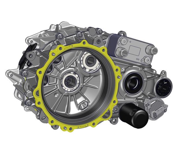
Oil Pumplink
The drive inverter controls the positive displacement electric oil pump, with feedback of motor electrical load and transmission fluid temperature. The operating temperature range is -40° C to 140° C. The electric oil pump is controlled based on many input conditions that allow improved drive unit efficiency, improved thermal system performance, and enables waste heat mode. This is achieved by transferring energy in the form of heat from the stator to the heat exchanger, where coolant is heated.
The oil pump is a component used to gain full control of the electronic engine control unit (ECU) hardware and firmware. The oil temperature is detected and reported by the oil pump thermistor. The temperature is allowed to vary within a given range. When the temperature exceeds the design limits, an alert signal will be triggered and the performance of the drive unit is limited. If there is insufficient flow of oil in the drive unit, the same outcome is to be expected.
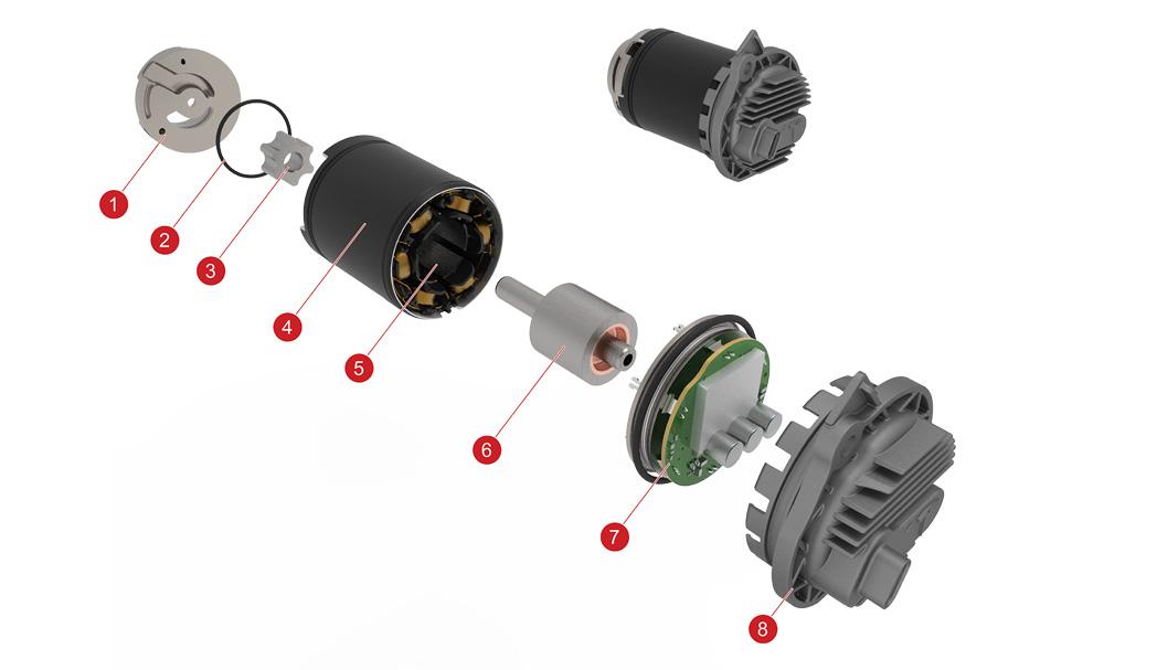 |
|---|
| 1. Pump Inlet 2. O-Ring 3. Inner Gear 4. Pump Housing 5. Stator 6. Rotor (Magnet) 7. Oil Pump ECU 8. ECU Cover |
| Oil Pump Assembly |
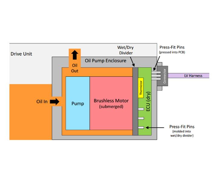 |
|---|
| Oil Pump Diagram |
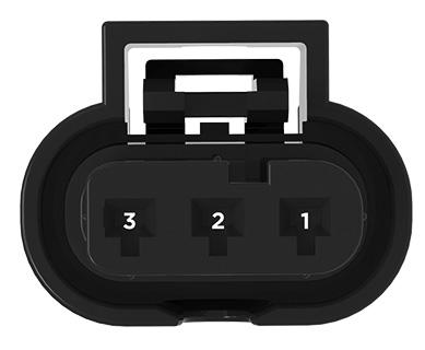 |
|---|
| Pin | Name | Type (device-defined, from the view of the Resolver) | Current |
|---|---|---|---|
| 1 | Switch +12V | Power In | 15mA Stall15mA Steady |
| 2 | Oil Pump Status | LIN | .2mA |
| 3 | END | GND Chassis | 15mA Stall15mA Steady |
Note
All pins are tin plated and sized the same: . Oil Pump Connector (Harness-Side Connector)
Motorslink
Overviewlink
There are different types of motors to serve different purposes, but all of them follow the same principles. The torque in every electric motor is created is by two magnetic fields that interact to each other, causing forces that rotate the rotor. Depending on the way that the necessary magnetic fields are created, the motors are divided in different categories.
The front drive unit is an asynchronous induction motor and rear drive unit is a synchronous permanent magnet motor (PM). The vehicle only needs one motor most of the time, which is the rear PM drive unit. The front drive unit is often idling. The induction motor drive unit is therefore most suitable as a front drive unit as it is lighter, lower cost and has lower losses when unpowered.
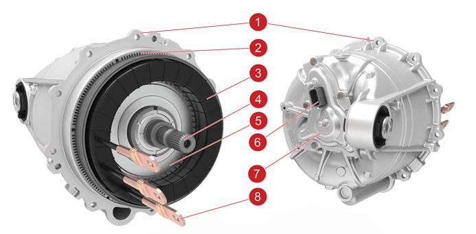
Permanent Magnet Motorlink
In permanent magnet motors, the magnets always have an established magnetic field in the rotor. When the stator windings are fed with 3-phase AC current, a rotating magnetic field is also established in the stator. If the stator was fed by DC current the magnets of the neighboring rotor magnetic pole would be attracted, causing the rotor to move until the magnets are aligned with the peak of the stator magnetic field. However, in this case, the rotor would stop moving after reaching this position. When applying AC current, the magnets of the rotor are “chasing” continuously the peak of the rotating magnetic field of the stator. The torque in the permanent magnet motors varies by controlling the amplitude of the stator current and the internal angle between the magnets and stator magnetic fields. The 2 fields rotate synchronously (there is no frequency difference between them) and this is the reason that this type of motors are also called Synchronous motors. If the current supply of the stator suddenly stops, there is still remaining magnetic field in the motor because of the existence of the magnets. This might lead to unexpected behavior of the motor during a fault case. The motor controller is responsible in detecting any abnormal operation and eliminate the impact that has to the system.
 |
|---|
| 1. Stator Housing 2. Stator Steel 3. Stator Windings 4. Rotor Shaft 5. Rotor Balance Ring 6. Resolver / Thermistor Connector 7. Resolver Cover 8. 3-Phase Lugs |
| Permanent Magnet Motor |
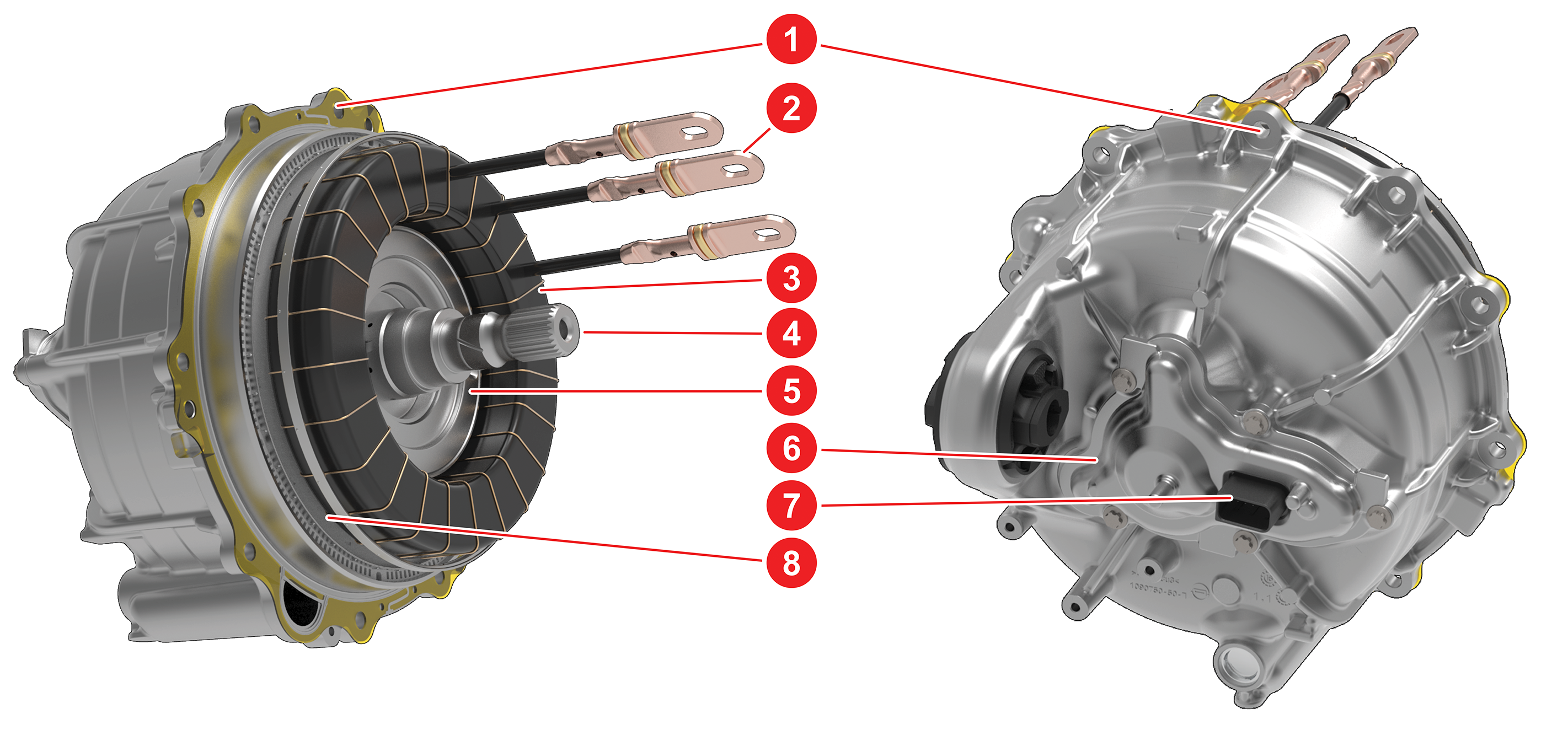
Induction Motorlink
An induction motor (3-phase induction motor or asynchronous motor) is an AC electric motor in which the electric current in the rotor needed to produce torque is obtained by electromagnetic induction from the magnetic field of the stator winding.
In an induction motor, the AC power supplied to the stator creates a magnetic field that rotates in synchronicity with the AC oscillations. The motor's rotor rotates at a somewhat slower speed than the stator field. The induction motor stator's magnetic field is therefore changing or rotating relative to the rotor. This induces an opposing current in the induction motor's rotor, in effect the motor's secondary winding, when the latter is short-circuited or closed through an external impedance. The rotating magnetic flux induces currents in the windings of the rotor. The torque can vary in induction motor by changing the amplitude of the stator AC current and the slip frequency. These 2 parameters are selected and commanded by the motor control, which is getting feedback from the accelerator pedal, the brakes, motor speed and the position of the rotor. When current stops flowing into the stator windings, the magnetic field collapses. The motor will continue spinning freely until stopped by mechanical losses, either internal or external(brakes, road grade, etc.).
 |
|---|
| 1. Stator Housing 2. 3-Phase Lugs 3. Stator Windings 4. Rotor Shaft 5. Cast Aluminum Rotor 6. Resolver Cover 7. Resolver/Thermistor Connector 8. Stator Steel |
| Induction Motor |
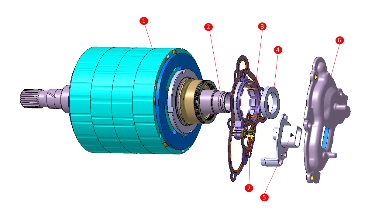
Motor Speed Sensor (Resolver)link
The drive units use a motor speed sensor known as a resolver. Unlike the encoders, which are speed sensors, the resolver directly measures the angle of the rotor. Speed measurements are derived from position measurements made over time. A resolver works similarly to a transformer where the amount of coupling between primary and secondary coils is determined by the angle of the resolver rotor (press fit onto the motor rotor) relative to the resolver stator (in the resolver cover assembly). The resolver stator is connected to the inverter control board via an external cable.
 |
|---|
| 1. Rotor 2. Rotor Shaft 3. Resolver Stator 4. Resolver Rotor 5. Resolver Bulkhead Connector 6. Resolver Casing 7. Resolver connector pins |
Stator Temperature Estimationlink
The stator temperature is not measured, but estimated using the oil pressure and temperature. Oil pressure and oil flow alerts can be expected when the stator is not operating under its nominal temperature range.