Chargers
Chargerlink
Overviewlink
The onboard charger converts AC power from the electric utility grid into DC power to charge the battery pack. The charger closely monitors the charging process and voltage characteristics of the electric grid to quickly and safely provide energy to the battery as requested by the user.
| Gen 1 Charger | Gen 2 Charger | Gen 3 Charger | |
|---|---|---|---|
| Model S vehicles built before December 2013 | X | ||
| Model S vehicles built between December 2013 - April 2016 | X | ||
| Model S vehicles built April 2016 and later | X | ||
| Model X | X |
Charger Componentslink
The main components of the charger are:
- Two or three phase boards, each including high power switching transistors and magnetics
- A Vehicle Interface (VI) board controlling the phase boards
- Liquid cooled heat sink
- Contactors for fast charging
- HV cabling and distribution
The charge port high voltage inputs and coolant inlets come in at the top of the charger. All low voltage connections enter through a single connector at the bottom of the charger.
The high voltage output exits the right side of the charger to the Rapid Splitter and battery. A high voltage output to the rear PTC heater option (if equipped) is also present from the top of the charger. The coolant exits from the bottom.
The Tesla Model X utilizes a 3rd Generation Charger (Gen 3 Charger).
Gen 3 Chargerlink
 |
|---|
| Gen 3 Charger |
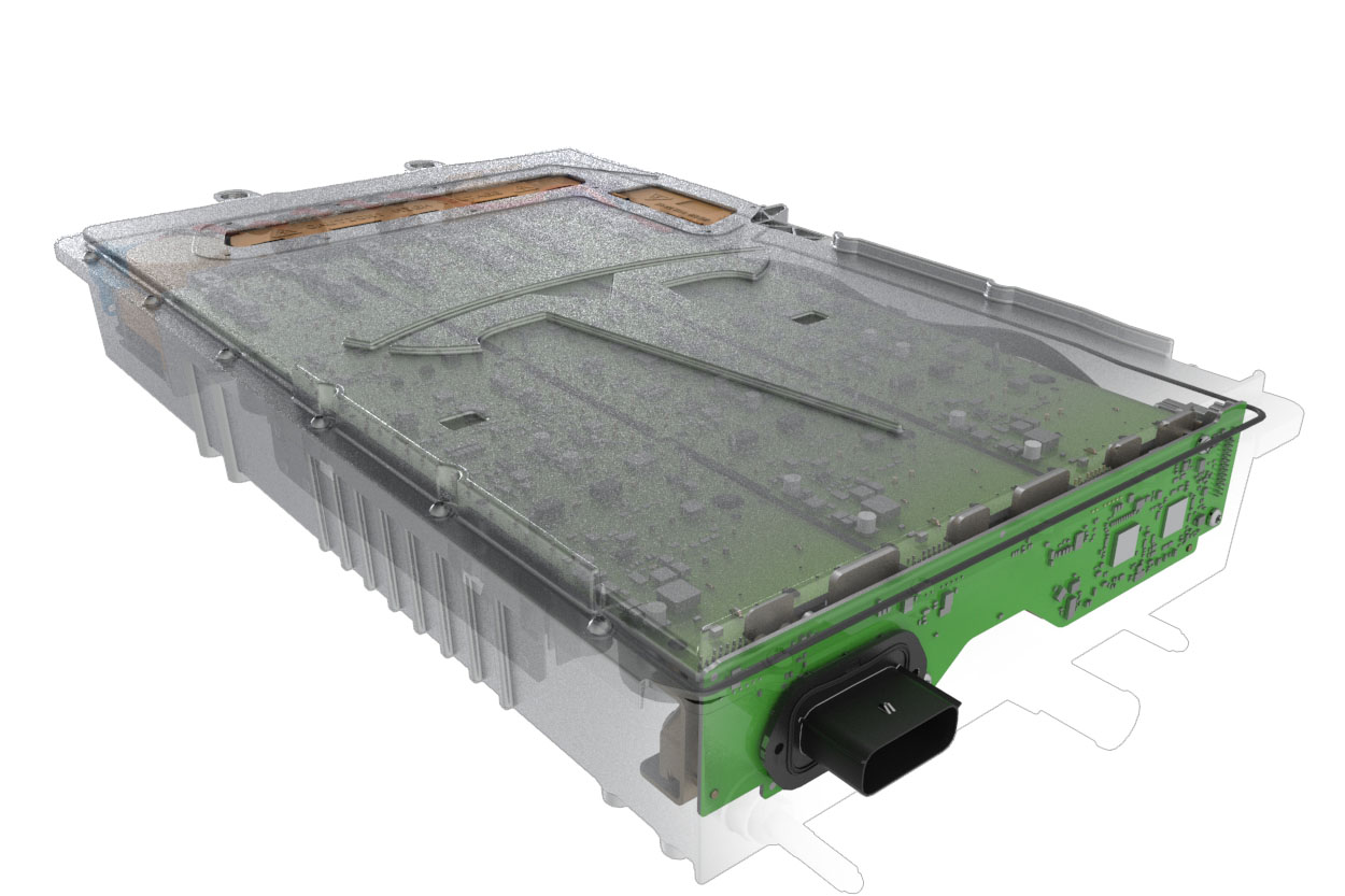
The Gen 3 Charger is a single onboard charger, as opposed to the dual charger configuration previously used on Gen 1 and Gen 2 Chargers. It is placed vertically near the left trunk area, directly below the Charge Port.
 |
|---|
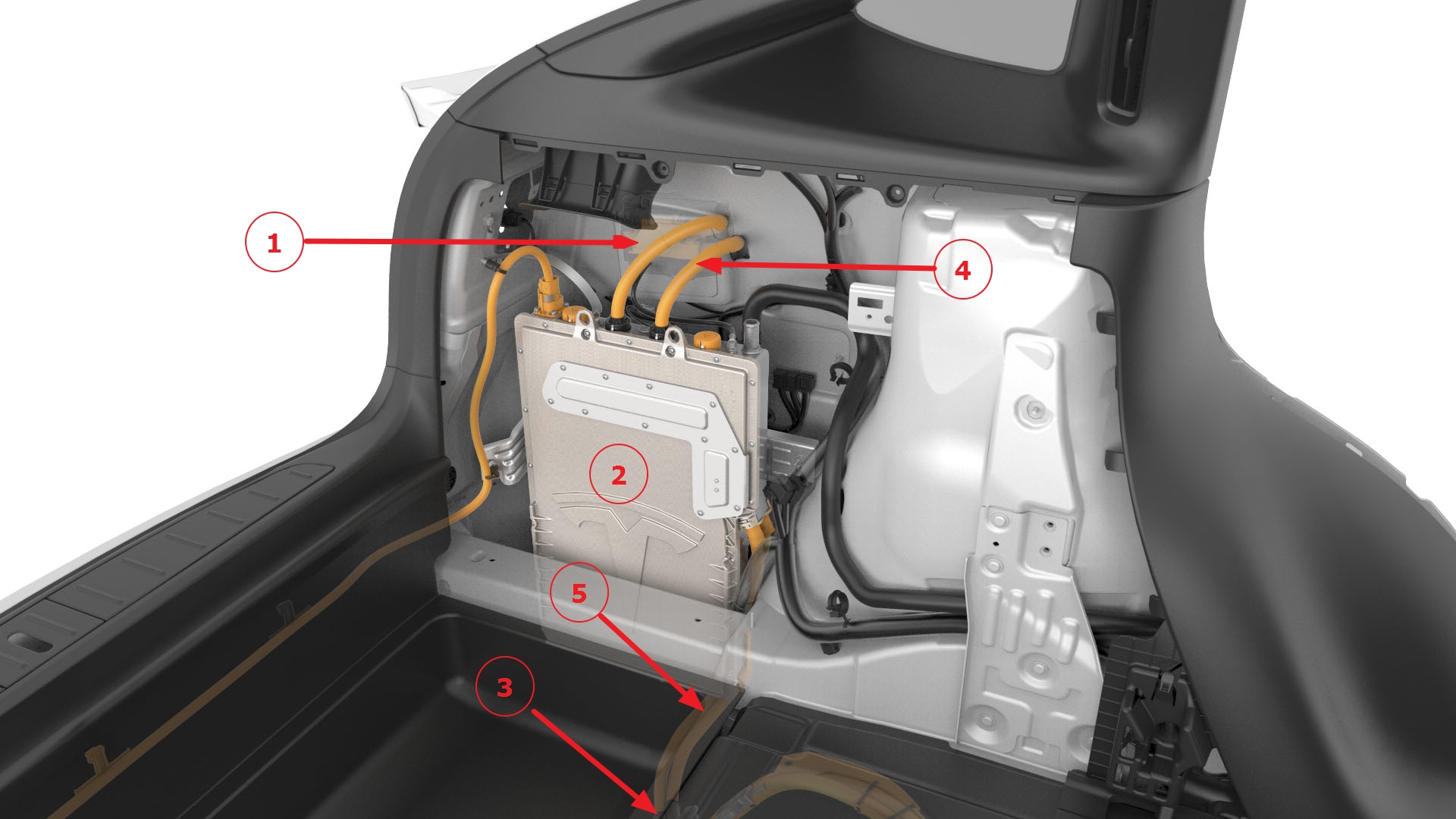
| 1. Charge Port 2. Charger 3. Rapid Splitter 4. HV cables between Charge Port and Charger (x2 in North America, x4 in EMEA/APAC) 5. HV cables between Rapid Splitter and Charger |
| Location of Charger in Model X |
The fast charge contactors are integrated into the Gen 3 Charger.
The Gen 3 Charger can charge at voltages up to 72A (72A on single-phase for the North America market, 24A per phase for three-phase markets). Gen 3 Charger inherited some previous high voltage junction box (HVJB) functionality, with the fast charge contacts located within the charger itself. Within Model S vehicles built in April 2016 and later, and Model X vehicles, the Gen 3 Charger is the only location within the HV system to check for the presence of High Voltage. Because the Gen 3 Charger is a standalone unit, there is no option to fit a secondary charger.
 |
|---|
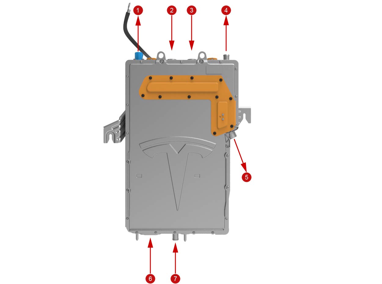
| 1. HV output to rear HVAC (blank in Model S) 2. HV Charge Port input (–) 3. HV Charge Port input (+) 4. Coolant outlet 5. HV output to Rapid Splitter 6. Low Voltage connections 7. Coolant inlet |
| Gen 3 Charger - Interfaces |
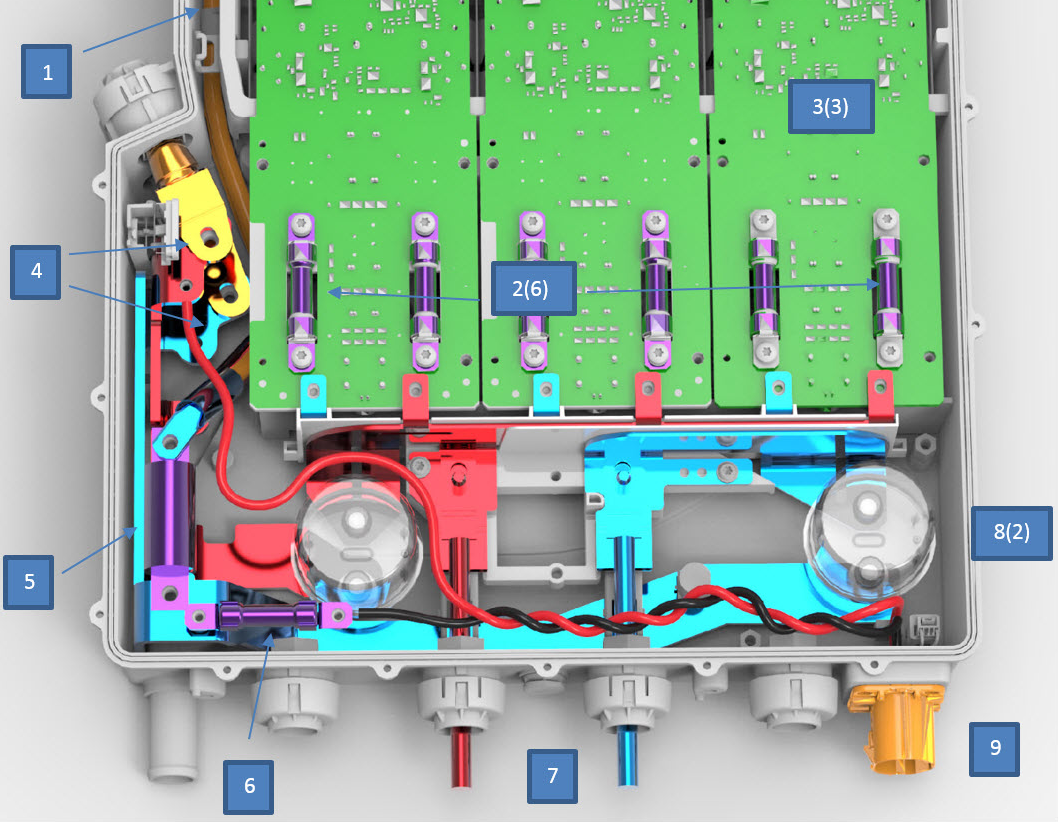
The image below displays the internal layout of the Gen 3 Charger:
Gen 3 Charger Internal Layoutlink
 |
|---|
| 1. HV DC output from converter 2. Phase fuses (x6) 3. Phase boards (x3) 4. HV to Rapid Splitter lugs 5. Main Charger fuse 6. Rear PTC heater fuse 7. HV (AC or DC) from Charge Port 8. Fast Charge contactors (x2) 9. HV output to rear HVAC |
| Gen 3 Charger - Internal Layout |
Communication with Charging Equipmentlink
The onboard charger handles the circuits responsible for communication with external charging equipment.
Control Pilot Signallink
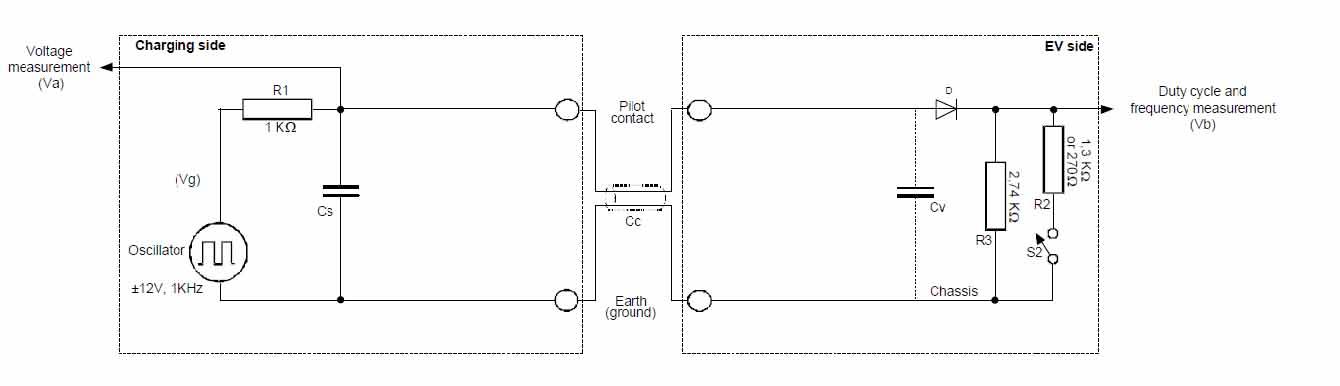
The control pilot (CP) signal is generated by the EVSE to tell the vehicle the maximum AC line current it is allowed to draw. The pilot signal is transmitted as a low voltage (max ± 12V) pulse width modulation (PWM) voltage signal sent through a single wire available in any modern charge cable. The duty cycle of the PWM tells the charger the exact current limit of the supply. This is standardized internationally in IEC 61851-1 and SAE J1772. The vehicle charger includes a switch (called S2) which the vehicle uses to request the charge equipment’s switching device to close, and thus allow the vehicle to draw current.
 |
|---|
| Control Pilot Circuit |
Tesla vehicles allow single wire CAN communication over the pilot wire for use with Supercharging, CHAdeMO adapter, and other Tesla charging equipment. Whenever CAN packets are transmitted over the pilot wire, the PWM signal is off, and the CAN messages tell the vehicle about state of supply and voltage/current limits. The pilot wire CAN communication also includes diagnostic information.
Proximity Circuitlink
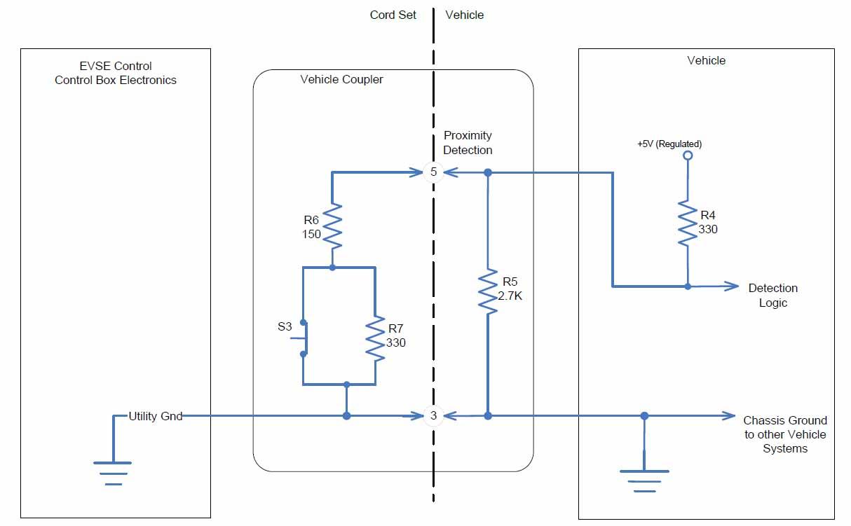
The Proximity circuit indicates that a charge cable is physically connected to the charge port. The purpose of proximity detection is to initiate the charging sequence, and to prevent movement of the vehicle while a cable is connected. The proximity circuit is shown on the diagram below:
 |
|---|
| Proximity Circuit |
In the “Not Connected” state, the proximity voltage is approximately 4.5V. In the “Connected” state, switch S3 is closed and the proximity voltage is approximately 1.5V. In the “Button Pressed” state, switch S3 is open and the proximity voltage is 2.8V. The proximity circuit connects to the on-board charger where voltage is monitored and interpreted.
The above voltage levels and diagram are standardized in SAE J1772. The J1772 cord set is also known as “type 1”. All Tesla charge cables worldwide use the type 1 proximity circuit as shown, including Mobile Connectors and Wall Connectors, regardless of the physical shape of the connector or adapter.
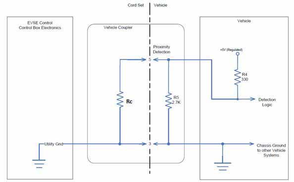
The three-phase vehicle charge port used in Europe, Middle East and parts of Asia Pacific can also be connected to third party three-phase cord sets, which are commonly known as “type 2”. These cables have a different cord set proximity circuit because they do not have a button on the charge cable handle. Instead, they encode the current capability of the cord set using four different proximity resistor values.
- 1500 ohm for 13A cables
- 680 ohm for 20A cables
- 220 ohm for 32A cables
- 100 ohm for 63A cables
On the diagram below, this “coding resistor” is shown as Rc.
 |
|---|
| Coding Resistor shown as "Rc" |
The diagram above shows the proximity detection logic in the charger has to accommodate seven different voltage levels depending on the charge cable type. These are summarized below:
| State | Nominal voltage on proximity wire to charger |
|---|---|
| No cable | 4.5V |
| 13A type 2 cable | 3.7V |
| 20A type 2 cable | 3.1V |
| Tesla/type 1 button pressed | 2.8V |
| 32A type 2 cable | 1.9V |
| Tesla/type 1 cable connected | 1.5V |
| 63A type 2 cable | 1.1V |
If the charger reads a voltage that is outside the allowed proximity voltage ranges, it throws a proximity rationality fault. The actual voltage read indicates the type of fault (open circuit, short circuit or proximity resistors faulty in cable or in vehicle).
Modes of Charginglink
Since the Battery Management System (BMS) monitors the health, State-of-Charge (SOC), and temperatures of the battery modules, the BMS decides whether the battery pack can be charged.
There are three charge modes available in the BMS:
- Power Mode: the onboard charger is enabled and commanded to output a certain power to the battery pack based on user request and available power from the charge equipment.
- Voltage Mode: the onboard charger is enabled, but the BMS contactors are open so no power flows to the battery pack. This mode is useful to enable charging a cold battery (colder than freezing), because it allows the user to warm up the battery using grid power.
- Fast charging (e.g. Supercharging): AC/DC power conversion takes place in an offboard charger, and the power converter in the onboard charger is disabled. The onboard charger plays an active role in managing the fast charge contactors.
Power Modelink
The battery management system (BMS) and charger interact via the powertrain (PT) CAN bus to control the charge process. The BMS requests the charger to start charging, provide a specified amount of power, and stop charging. The charger takes the requested power as an input, and manages the charger’s three internal phase boards to provide DC power to the battery.
For more information on PT CAN bus, see Controllers and Wiring..
The vehicle charging process follows the sequence below:
- The charge port door is opened, and the cable is inserted into the vehicle inlet. The charger measures the proximity signal from the proximity pin in the charge port, and sends this information via the PT CAN bus. This signal communicates to all powertrain components that a charge cable is connected.
- When the external charge equipment is ready to provide power, it sends a pilot signal indicating the maximum allowed current (based on the conductor of the charge cable and the installation that it is connected to). The charger reads the current limit, and sends it to the BMS. The BMS also reads the current limit indicated by the user on the MCU. The BMS always assumes the lower of these line current values.
- At this point, the BMS can estimate the amount of power available for charging. It does not know exactly how much power will be available, because voltage has not yet been supplied by the charge equipment and the charger is still in Idle Mode. If the BMS finds that the battery is ready to be charged, the BMS switches to Charging Mode, and tells the charger that it may continue starting the charging process. The requirements for the BMS to enable charging are that no BMS or charger faults are present, battery module temperatures are within allowable limits, the battery is not full, and the user has requested charging.
- When the BMS allows the charger to begin charging, the charger tells the charge equipment to close its switching device and thereby apply grid voltage to the charger. This is referred to as “EVSE accept”. It involves actuating switch S2 in the pilot circuit, which changes the amplitude of the pilot circuit PWM signal. The charge equipment detects this condition and closes its switching device as described in previous section.
- Once the supply side switching device is closed, the charger measures voltage at its AC input and can determine the grid configuration (single-phase / three-phase / delta), as well as update the available power estimate for the BMS. With voltage present at the charger’s input, the phase boards are enabled and prepared to provide power. This sub-sequence is called “precharging” and is described in the next section.
-
After the phase board has precharged and is ready to begin charging, the BMS commands the charger to output power.
Note
The charger operates in a Constant Power mode because the DC battery voltage increases during charging. Because of this, the DC output current decreases, but the output power remains constant.
The charging process can end in multiple ways:
- The user requests charging to stop via the mobile app, pressing a button on the MCU, or using the key fob.
- The user presses the charge handle button.
- Reaching full battery at 100% SOC.
- Reaching the charge termination percentage set on the MCU.
- Wall power is removed.
- Faults set by the BMS, charge port, charger, charge equipment or Gateway.
It is worth noting that at a certain point before the battery reaches 100% SOC, the BMS commands the charger to run in Constant Voltage Mode to avoid exceeding the battery voltage limits.The Constant Voltage Mode entails decreasing current and power as SOC increases, which is expected operation. This is similar to the gradual charge current reduction observed during fast charging and Supercharging; however, since the onboard charger transfers less power, the SOC at which Constant Voltage Mode is entered is much higher, typically >95%.
Voltage Modelink
When the battery is at a temperature below freezing, it needs to warm up in order to accept charge power. If the available AC supply power is lower than the power needed to heat up the pack (which can be up to 4.5 kW), the battery would have to discharge in order to charge, which is undesirable.
Since the battery coolant heater is a simple resistive load connected across the HV bus, the battery heater power is a function of the square of the bus voltage. Therefore, the battery heater requires less power if it is run with lower voltage. The charger voltage mode is designed to do just that – instead of closing BMS contactors and running the battery heater at high power, the BMS contactors remain open, and the charger runs the HV bus at lower voltage (down to 180 VDC), which allows running the battery heater on grid power only. As soon as the battery is warm enough to accept charge, the BMS commands the charger to switch out of voltage mode and into power mode, and the BMS contactors close to charge the battery. Voltage mode is supported for AC supply power down to 1.7 kW.
Fast Charge Modelink
The onboard charger manages operation and fault checking of the fast charge contactors, which are used to route DC power from the combined ACDC charge port to the battery pack when fast charging. Single phase charge ports have two incoming HV lines, requiring two FC contactors. Three-phase charge ports have four incoming HV lines and four fast charge contactors. The BMS supplies power for switching the FC contactors, and the charger controls the actuation of the fast charge contactors. The charger performs the following checks before the fast charge contactors are closed:
-
Check that fast charge contactors are not welded. There are two types of FC contactor weld check: static check and dynamic check.
- The static check utilizes a low-voltage auxiliary relay mechanically linked to the high-current contactor to ensure that the contactor is in the Commanded state (open or closed).
- The dynamic check measures DC voltage at the charge port inlet when the vehicle is not charging. In the rare case that fast charge contactors are detected to be welded, the vehicle cannot close BMS contactors and cannot open the charge port door. The charger assumes that the fast charge contactors are welded if it receives irrational sensor readings, which means false positive detections are possible.
-
Check that voltages across the fast charge contactors match, and if so, close the fast charge contactors.
To avoid contactor arcing and inrush currents, the DC voltages must match on both sides of the contactors before they are closed. Once voltage matches, the BMS supplies contactor power so the charger is able to actuate the contactors.
When fast charging finishes, the charger opens the fast charge contactors when commanded by the BMS, and performs the FC contactor weld check again.
System Specificationslink
Gen 3 Charger Specificationslink
| Max input AC current | 24A per phase |
|---|---|
| Input AC voltage | 85-300 VAC rms |
| Number of phases | 3 |
| Max input power at 120V | 8.6 kW |
| Max input power at 230V | 16.5 kW |
| Max input power at 240V | 17.3 kW |
| Efficiency | >94% |
| Output DC voltage | 280 VDC – 410 VDC |
| Max allowed voltage drop | 14% regardless of region |
| Weight | 17 kg |
| Dimensions (W x L x D) | 342 mm x 528 mm x 89 mm |
High Voltage Distributionlink
Unlike the Gen 1 Charger and Gen 2 Charger, the Gen 3 Charger does not have a separate HVJB. The charger and junction box are combined into one enclosure. The fast charge contactors also reside inside the charger enclosure.
There are 11 fuses inside the charger: two for each phase board on the AC input side, one fuse on the DC output side of each phase board, one fuse for the rear PTC heater, and one fuse for the charger DC connection to the Rapid Splitter. The phase boards have no relays.
Phase Boardslink
The electronics in the charger are comprised of 2 or 3 identical phase boards that are rated for 24A per phase on the AC input.
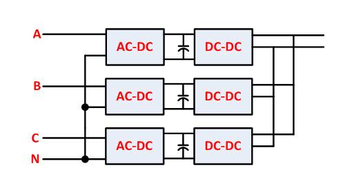
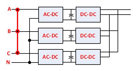
Although the phase boards are identical across the three-phase and single-phase versions of the charger, the routing of the incoming AC wires is different. The three-phase version connects each incoming phase to one phase board, and connects the neutral to all three-phase boards. The single-phase version connects all three-phase boards in parallel to phase and neutral. See the diagram below.
 |
|---|
| Three-phase Charger |
 |
|---|
| Single-phase Charger |
This means that the single-phase version of the charger requires two incoming power lines from the charge port, and the three-phase version requires four incoming power lines.
Phase Boardslink
Although the phase boards are identical across the three-phase and single-phase versions of the charger, the routing of the incoming AC wires is different. The three-phase version connects each incoming phase to one phase board, and connects the neutral to all three-phase boards. The single-phase version connects all three-phase boards in parallel to phase and neutral. See the diagram below.
|
|---|
| Three-phase Charger |
|
|---|
| Single-phase Charger |
This means that the single-phase version of the charger requires two incoming power lines from the charge port, and the three-phase version requires four incoming power lines.
Serviceabilitylink
Retry Behaviorlink
The charger is designed to require no user interaction for operation. It is fully controllable through the CAN bus.
Since it is vitally important to be able to charge an electric vehicle, the charger implements retry strategies, and is designed to continue charging even if parts of it have failed or become unresponsive. Charger retry behavior is occasionally adjusted based on field feedback and hardware improvements.
If a phase board experiences a fault and sets an alert, the phase board retries charging immediately. If it fails again, the charger sets this particular phase board in a faulted state, but the remaining active phase boards continue charging. If the VI board experiences a fault that relates to all phase boards, such as a faulty charge cable or wall power transients, the VI board retries charging up to three times. If it is unable to restart charging after three attempts, it enters a faulted state.
Troubleshootinglink
For Charging alerts, a customer-facing user interface (UI) feature directs the user to the appropriate section in Troubleshooting Alerts in the Owner's Manual.
There are two ways to re-initiate charging:
- The BMS clears charger faults periodically (typically every 10 minutes),
- or the charge cable can be removed from the vehicle and re-inserted.
The charger monitors the proximity signal; when it is disconnected, all faults are cleared. Charging is restarted when the cable is reinserted.
Some HV faults (such as a suspected fast charge contactor weld condition) can only be cleared when the charge port door is closed, and the BMS closes battery contactors so the charger and the BMS can measure that the HV bus is safe. Therefore, if a charge fault is not cleared by removing the charge cable, also attempt to close the charge port door and start the vehicle by pressing the brake pedal.
Note
If the charger is in a faulted state, this does not mean the charger is broken.
Poor electrical grid connections, old outlets, grid transients, or faulty charge equipment can cause the charger to start and stop repeatedly. In these cases, the alerts set by the charger must be carefully inspected and understood to educate the user accordingly. It is ideal to try charging on a different outlet or in a different location to ensure the charger operates as designed. Electrical grid transients, distortion, brown-outs or blackouts, and other types of grid faults can be experienced locally such as in a household, or at a larger regional scale such as a neighborhood or city.
For safety reasons, if the charger experiences high grid line impedance resulting in a voltage drop of more than 14%, the charger immediately moves to a faulted state without retrying and can only be restarted by removing the charge cable and reinserting it. This is done to ensure that the user is aware of this particular charge fault and force the user to take appropriate actions to reduce the line voltage drop. Actions that the user can take include turning down the charge current, switching off other electric equipment nearby, moving to a different location, or having an electrician inspect the installation.
The charger is active during both AC and DC charging; however, measurements, alert thresholds, and the state machines are different between AC and DC charging. This means that if a charger is unable to AC charge, DC charging may work. If a charger is the cause of DC charging not working, AC charging may work.