Filter Selection
Please select applicable umc
Please select applicable wc
External Charging Componentslink
Last updated: February 28, 2024
Customer-facing information, installation guides, and troubleshooting tips can be found on Tesla Support.
Universal Mobile Connector, 1st Generation (Gen 1 UMC)link
Overviewlink
The UMC is designed to give the added flexibility of charging the vehicle while on the road from a standard wall outlet. It is small enough to carry in the trunk. It operates on 110 - 240 VAC and gives a maximum of 40A of current when connected to a 240V/50A source. Maximum charging current is 12A when connected to a 110V/15A source.
Note
If the electrical outlet is unable to provide the current demanded by the Universal Mobile Connector (UMC), the circuit breaker protecting the electrical outlet might trip. If this happens, reduce the maximum current limit via the touchscreen.
Universal Mobile Connector Troubleshootinglink
 |
|---|
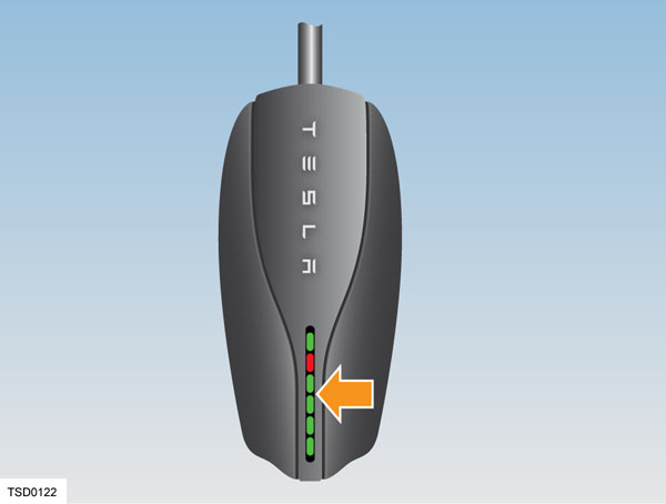
The UMC has a number of colored lights. Any problems during charging can be quickly identified by observing which light is flashing and the number of flashes. The following table provides more detail.
| Green lights | Red light | What it means | What to do |
|---|---|---|---|
| All lights on | Off | Charging in progress | Nothing. The UMC is successfully charging. |
| Top light on | Off | UMC is powered but not charging | Make sure the UMC is plugged into the vehicle. |
| Off | 1 flash | Ground fault: current is leaking through unsafe path | Should reset after 15 minutes. If not, make sure no one is touching the vehicle and then press the RESET button. |
| Off | 2 flashes | UMC failed the self test | Disconnect the UMC and press the RESET button. Reconnect the UMC. If the error persists, disconnect the UMC from the vehicle and power outlet. Reconnect to the power outlet and then to the vehicle. |
| Off | 3 flashes | Contactor failed | Disconnect the UMC from the vehicle and wait 10 seconds before trying again. If the problem persists, contact Tesla. |
| Off | 4 flashes | Ground lost | Make sure the UMC is properly grounded. If using a 120V outlet, make sure the hot and neutral pins are wired correctly. If uncertain, ask an electrician or plug a standard electrical receptacle tester into the outlet. |
| Off | 5 flashes | Sense circuit fault | Make sure the UMC adapter is attached properly. |
| Off | 6 flashes | Thermal fault | Consider charging inside a garage. |
| Off | 7-10 flashes | Pilot out of tolerance | Check charge connector for water intrusion. Blow out with compressed air. |
| Off | Off | Power lost | Disconnect the UMC and check that it has power. |
Universal Mobile Connector, 2nd Generation (Gen 2 UMC)link
Overviewlink
The 2nd generation Universal Mobile Connector (Gen 2 UMC) is available worldwide, and supports charging from single phase wall outlets up to 32A. Like the 2nd generation Wall Connector, the Gen 2 UMC has the ability to communicate over Single-Wire CAN (SWCAN), which is useful to diagnose issues, update firmware, as well as record the health and genealogy of the unit and adapter. The Gen 2 UMC is slightly smaller compared to the previous Gen 1 and Gen 1.5 UMC, and Gen 2 UMC is standard equipment with all vehicles. Gen 2 UMCs feature so-called Smart Adapters, which monitor the temperature of the plug and adapter assembly during charging.
Gen 2 UMC provides the customer with a safe mechanical and electrical interface between a regular household outlet and the vehicle inlet. The UMC has a contactor, controlled by a microcontroller, that is only powered when the vehicle requests charging. The UMC can detect many types of unsafe charging conditions before and during charging, and halt charging should it be required.
Specifically in Europe and Asia, the Gen 2 UMC is a single-phase only product. Installing a hardwired charging station (such as a Tesla Wall Connector) at the location where a vehicle frequently charges always gives the best charging experience.
Specificationslink
- Voltage and Wiring: 100-240V nominal AC single-phase
- Grid Frequency: 50/60Hz
- Cable Length: 20' (6 m)
- Dimensions:
- Height: 179.8 mm
- Width: 81.7 mm
- Depth: 47.3 mm
- Operation Temperature: -22°F to 122°F (-30°C to 50°C)
- Enclosure Rating: IP65
- Conformance: SAE, UL, IEC
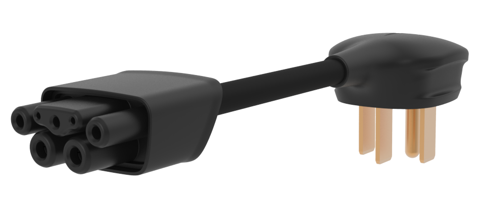
Component Descriptionslink
 |
|---|
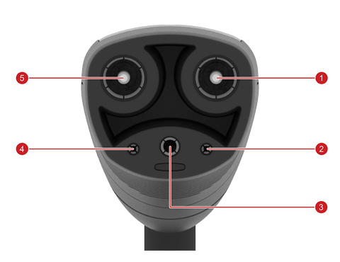
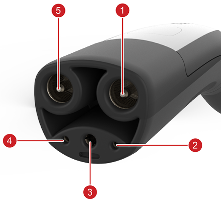
| 1. L2/N 2. Pilot 3. PE 4. Prox 5. L1 |
| Vehicle Connector and Pinout, North America |
 |
|---|
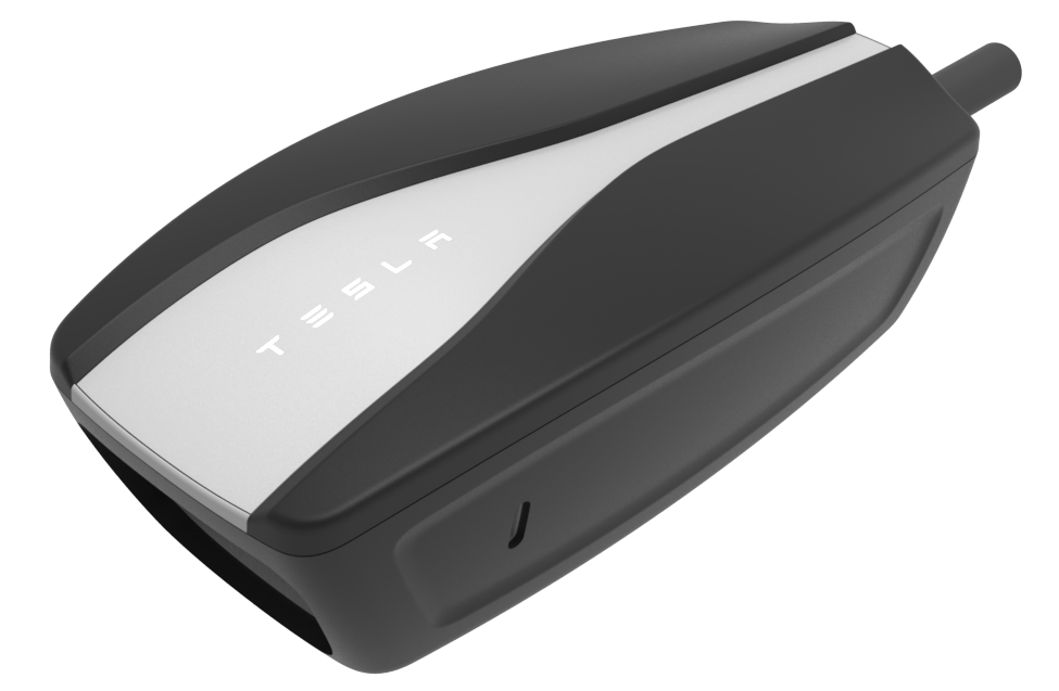
| Inline Unit |
 |
|---|
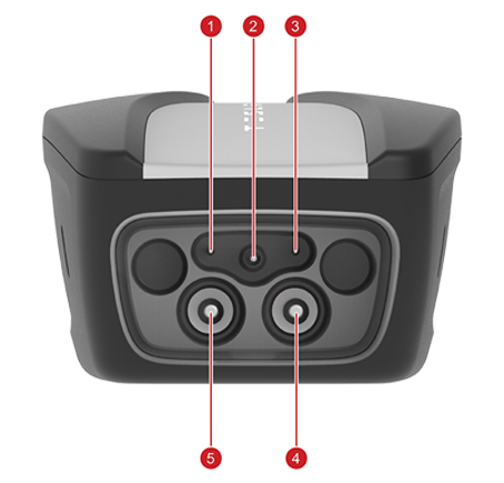
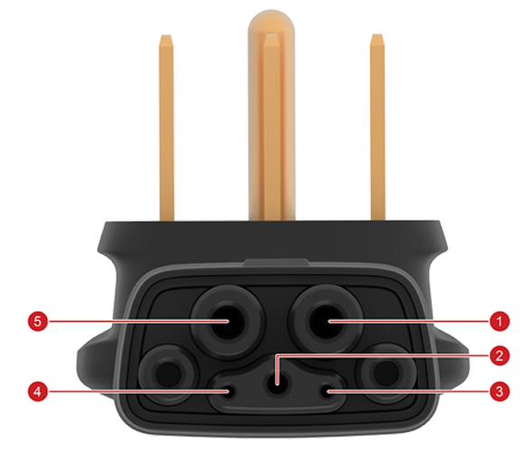
| 1. Sense 2. PE 3. Ground 4. L1 5. L2/N |
| Inline Unit Adapter Receptacle Pinout |
 |
|---|
| Example Smart Adapter, NEMA 14-50 |
 |
|---|
| 1. L2 2. PE 3. GND 4. Sense 5. L1 |
| Smart Adapter Pin-Out |
Note
The pin-out is the same for all adapters.
Available adapterslink
Note
Refer to the parts manual for latest part numbers and availability of adapters per region.
Table 1. North America
| Adapter | Max charge current |
|---|---|
| NEMA 14-50 | 32A |
| NEMA 5-15 | 12A |
| NEMA 14-30 | 24A |
| NEMA 10-30 | 24A |
| NEMA 6-50 | 32A |
| NEMA 6-20 | 16A |
| NEMA 6-15 | 12A |
| NEMA 5-20 | 16A |
Note
For NEMA outlets, the number after the dash is the peak current of the outlet. For continuous current applications like EV charging the current is derated to 80% of its peak.
Table 2. Europe and Middle East
| Adapter | Max charge current |
|---|---|
| Schuko | 13 A |
| 16A blue | 16 A |
| 32A blue | 32 A |
| UK | 10 A |
| Swiss | 10 A |
| Italy | 13 A |
Table 3. Asia Pacific
| Adapter | Max charge current |
|---|---|
| AU 10 | 8 A |
| AU 15 | 12 A |
| Guobiao 10 A | 8 A |
| Guobiao 16 A | 13 A |
| JWDS-0033 Japan | 16 A |
| Schuko | 13A |
Behaviorlink
Communication Overviewlink
The Gen 2 UMC operates in two communication modes: SWCAN and PWM. The latter is sometimes also known as legacy pilot, which is also used by third party AC charging stations and when charging third party vehicles. SWCAN allows for CAN communication between the inline unit and Tesla vehicles. The physical signaling is identical to Supercharging and Gen 2 Wall Connector, however actual CAN message content is different.
Once the Gen 2 UMC connects to a vehicle, it detects whether it's connected to a Tesla vehicle or a third party vehicle, then switches into the appropriate signalling mode. If it is connected to an outlet and not charging, then the Gen 2 UMC will enter a detecting mode while waiting for a charge request from a vehicle.
Legacy Pilot Operationlink
The traditional Pulse Width Modulation (PWM) pilot scheme, or legacy pilot, uses a low voltage -12/+12 V PWM signal to indicate allowable charge current by setting the duty cycle of the signal. Additionally, the vehicle can modify the positive amplitude of the PWM signal through the use of electrical switches, located in the charge port ECU for Model 3/Y and in the onboard charger or the charge port ECU for S/X.
Hint
If the charge port ECU is located separately from the charge port itself, then the charge port ECU terminates SWCAN. The vehicle can use this to indicate certain states to the charge equipment.
The states as per SAE/IEC standards are:
- State A: UMC is connected to an outlet but not to a vehicle
- State B1: UMC is not ready to supply power
- State B2: UMC is ready to supply power. Vehicle is not ready to receive power.
- State C1: UMC is not ready to supply power. Vehicle is ready to receive power.
- State C2: UMC is ready to supply power. Vehicle is ready to receive power.
- State E: The UMC is unpowered.
- State F: UMC is at fault, and outputs -12V continuously, no PWM (aka 0% duty cycle).
Once charging is in state C2 the UMC will close its AC contactors, and the vehicle will start charging.
Single Wire CAN (SWCAN) Operationlink
SWCAN section in Charge Port.
The standardized charging states are also used during SWCAN. SWCAN uses a hand-shake process for determining that it is connected to a Tesla vehicle. When connected to a vehicle, the UMC's pilot will enter into State B2, with 5% duty cycle, which means the UMC is requesting SWCAN communication with the vehicle. A Tesla vehicle will recognize this request, accept it, and change the UMC pilot state to C2, before switching the SWCAN transceivers to start CAN communication with the UMC. Once in SWCAN mode, the UMC will switch off the pilot PWM generator. A third party vehicle will not be able to establish and authenticate a digital communication with the UMC.
Once SWCAN communication has been established the charging states as listed above are communicated digitally.
Safety Checkslink
The Gen 2 UMC has many safety checks:
- WELD – check if the contactors are welded. Looks for output voltage while contactors are open
- GFCI – check if current leaks to ground. Trip threshold is greater than 17mA residual fault current
- GMI – measures ground wire resistance. Trip threshold is greater than 1 MOhm between lines and ground indicating a disconnected ground pin in the outlet
- OV – over voltage test. Trip threshold greater than 305V
- UV – under voltage test. Trip threshold less than 40V
- OTEMP – detect over temperature
- TEMP – detect temperature fold back condition
- SA – smart adapter test. Fails if communication could not be established to Smart Adapter
- PILOT – check pilot signal rationality. Applies to legacy pilot scheme only
- PROX – check proximity signal rationality. Applies to SWCAN only
- SELF – conduct self-tests to check if HW is properly operating
- CRC – check if FW CRC is correct
The safety checks are run continuously in almost all operating states, with a few exceptions when they don't provide value/additional safety.
Thermal Foldbacklink
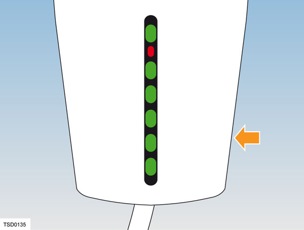
Gen 2 UMC measures temperature in 4 locations: in the adapter near the electrical outlet, inside the inline unit (near its connector and inside the internal microcontroller), and inside the vehicle connector. Gen 2 UMC reduces allowable charge current when temperatures measured by any of the temperature sensors exceeds defined thresholds. This mechanism is known as thermal foldback. The current is reduced in two steps, the first is known as the foldback limit at which point current is reduced by 50%, and the unit blinks red while streaming green to indicate it continues charging. The second step is a shutoff limit at which point charging is interrupted. In case the inline unit cannot communicate with the smart adapter to measure temperatures in the electrical outlet the max charge current is reduced to 8A to allow for emergency charging.
Firmware Updateslink
The Gen 2 UMC firmware is able to update when powered and connected to a Tesla vehicle. The Gen 2 UMC firmware is packaged with the vehicle firmware as part of a vehicle firmware update, and may be loaded on to the Gen 2 UMC the next time the Gen 2 UMC is connected to the vehicle, charging has finished, and given the update is required. Some vehicles may have disabled UMC updates. The Gen 2 UMC utilizes a triplet firmware versioning scheme, e.g. "1.7.2". Refer to the Service Manual for the exact steps to update a Gen 2 UMC.
Serviceabilitylink
The Gen 2 UMC and adapters are not serviceable internally and must be replaced if broken. Only replace the broken part, i.e. don't replace the adapter if the Gen 2 UMC unit is at fault and vice versa.
Best practices exist for diagnosing the product. In case of failure to charge using a Gen 2 UMC try:
- Charging on a different outlet at the same location, and a completely different location. This is because bad building wiring installations or grid disturbances may affect larger areas.
- Charging with a different adapter. If this fixes the issue then recreate this behavior in the service center (or another known good location), and if failure confirmed, replace the faulty adapter, but don't replace the Gen 2 UMC unit.
- Charging with a different Gen 2 UMC unit, using the same adapter. Again, try this at the service center to confirm. If a new Gen 2 UMC unit fixes the issue, replace the faulty unit but do not replace the adapter, unless there is suspicion that the failure is somehow linked to the use of this particular adapter.
- Always try to read out the alert given by the vehicle, and look it up in Toolbox for detailed troubleshooting information. Use UI alert messages for troubleshooting.
- If the alert is unavailable for any reason, then attempt to read out the blink code and record it. Troubleshooting steps are available in the UMC owners manual, and in Toolbox based on either alerts or blink codes.
Note
The Gen 2 customer facing UMC alert messages are prefixed UMC_
For UMC_ alerts, a customer-facing user interface (UI) feature directs the user to the appropriate section in the Owner's Manual.
Wall Connector, 1st Generation (Gen 1 Wall Connector)link
Overviewlink
The Wall Connector, also known as the High Power Wall Connector (HPWC), is installed on a 240 volt circuit and features a charging cable terminated in a 5-pin charge connector. The Wall Connector supplies up to 20 kW (80A at 240V).
The Wall Connector enables vehicles equipped with twin onboard chargers to charge twice as fast as vehicles equipped with a single charger. The Wall Connector ensures safe charging by using a switch that only connects line voltage to the vehicle when all conditions for charging are met. With 20 kW of power, a vehicle equipped with two chargers can recover 62 miles of range per hour of charging.
Self-Monitoring and Recoverylink
The Wall Connector has a ground monitoring circuit that continuously checks for the presence of a safe ground connection and automatically recovers from faults. Manual testing and resetting is not required. Temporary problems such as ground faults or utility power surges are overcome automatically, without the customer’s attention.
If a ground fault circuit interrupter fault occurs that interrupts charging, the Wall Connector automatically tries to clear the fault and re-attempts charging. This ensures that the vehicle is charged and ready for use when needed. If the problem is immediately sensed a second time, the Wall Connector waits 15 minutes before trying to charge. This process repeats eight times and if all attempts are unsuccessful, power is removed and no further attempts are made. In this case, a red error light on the front panel displays (See the Wall Connector Troubleshooting section for more information.). If a red error light displays, power off the Wall Connector and power it back on again.
Power Outageslink
If a power outage occurs, the Wall Connector automatically resumes charging when power is restored. If the charging cable is plugged into the vehicle when power is restored, the lights blink and the unit does not energize the charging cable for approximately 15 seconds to 3 minutes. This prevents the utility grid from experiencing a large surge when power is restored, allowing electric vehicles to begin drawing current at random times rather than all at once.
Wall Connector Self Test Modelink
Note
Always consult the installation guide for the Wall Connector being diagnosed.
- Cut the power supply to the Wall Connector and remove the front cover.
-
Use a pointed non-conductive implement, such as a plastic pen, to set the dip switches to the test setting as shown.
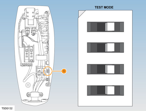
1. Dip switches Wall Connector Self Test Mode -
Locate the front cover over the top hinge.
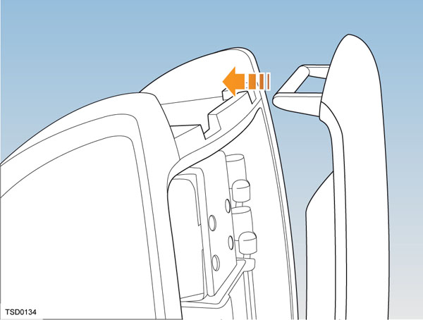
-
Turn on the power and hold the RESET button (shown below with an arrow) for five seconds. The contacts should audibly close and the lights sequentially display green.
If the red light is on or flashing, refer to Wall Connector Troubleshooting.
If the red light is not on or flashing, refer to Setting Operating Current.
Wall Connector Troubleshootinglink
| Green lights | Red light | What it means | What to do |
|---|---|---|---|
| All lights on | Off | Charging in progress | Nothing. The Wall Connector is successfully charging. |
| Top light on | Off | Wall Connector is powered but not charging | Make sure the charge connector is plugged into the vehicle. |
| Off | 1 flash | Ground fault: current is leaking through unsafe path | Should reset after 15 minutes. If not, make sure no one is touching the vehicle and then press the RESET button. |
| Off | 2 flashes | Wall Connector failed the self test | Disconnect the Wall Connector and press RESET button. Reconnect the Wall Connector. If the error persists, disconnect the Wall Connector from the vehicle and power outlet. Reconnect to power outlet and then to the vehicle. |
| Off | 3 flashes | Contactor failed | Disconnect the Wall Connector from the vehicle and wait 10 seconds before trying again. If the problem persists, contact Tesla. |
| Off | 4 flashes | Ground lost | Make sure that the Wall Connector is properly grounded. Make sure the hot and neutral pins are wired correctly. If uncertain, ask an electrician. |
| Off | 5-6 flashes | Wall Connector requires servicing | Contact Tesla. |
| Off | 7-10 flashes | Pilot out of tolerance | Check the charge connector for water intrusion. Blow out with compressed air. |
| Off | 8 or more flashes | Wall Connector requires servicing | Contact Tesla. |
Setting Operating Currentlink
Note
Always consult the installation guide for the Wall Connector being diagnosed.
Warning
Risk of electrical shock. Before continuing, use a voltmeter to confirm that no power is available at the service wiring or terminals.
- Turn off the power source at the breaker.
- Open the front cover.
- Use a pointed non-conductive implement, such as a plastic pen, to set the dip switches to an appropriate operating current based on the type of breaker being used.
- Reinstall the front cover and turn on the power source to the Wall Connector.
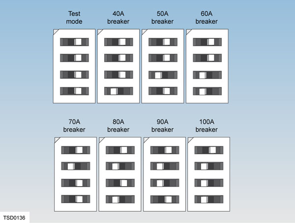 |
|---|
| Dip switch settings for type of breakers |
Wall Connector, 2nd Generation (Gen 2 Wall Connector)link
Overviewlink
The Tesla Gen 2 Wall Connector is available globally. In single phase markets (North America, Japan, Taiwan, South Korea), the Gen 2 Wall Connector is equipped with a Tesla vehicle connector. In China, it is equipped with a Guobiao AC vehicle connector, and in the rest of the world is equipped with an IEC Type 2 vehicle connector. In addition to the capabilities of other high power AC charging stations, the Gen 2 Wall Connector can communicate over Single-Wire CAN (SWCAN) which is useful for alerts and diagnostics. The Gen 2 Wall Connector can share current between a maximum of 4 units to allow installation of many Wall Connectors at sites with limited power availability.
Specificationslink
Single-Phase Unitlink
- Voltage and Wiring:
- 277V AC single-phase wye
- 208V or 240V AC split-phase, single-phase delta or wye
- Configurable Current: 80A, 72A, 64A, 56A, 48A, 40A, 36A, 32A, 28A, 24A, 20A, 16A, 12A
- Grid Frequency: 50/60 Hz
- Cable Length: 8.5' (2.6 m) and 24' (7.4 m)
- Gen 2 Wall Connector Dimensions: Height: 15.0’’ (380 mm) Width: 6.3’’ (160 mm) Depth: 5.5’’(140 mm)
- Top Entry Bracket Dimensions: Height: 10.8 in (275 mm) Width: 5.1 in (130 mm) Depth: 2.0 in (50 mm)
- Weight (Including Bracket): 20 lbs (9kg)
- Operating Temperature: -22°F to 122°F (-30°C to 50°C)
- Storage Temperature: -40°F to 185°F (-40°C to 85°C)
- Connector Type: Tesla
- Enclosure Rating: Type 3R
- Approval Agency: cULus listed for United States and Canada under file number E354307, FCC part 15.
- Ventilation: Not Supported
Three-Phase Unitslink
- Voltage and Wiring:
- 230V AC single-phase
- 400V AC three-phase
- 230V AC three-phase (Norway/Belgium)
- Configurable Current: 32A, 25A, 20A, 16A, 13A, 10A, 8A, 6A
- Grid Frequency: 50/60 Hz
- Cable Length: 8.5' (2.6 m) and 24' (7.4 m)
- Gen 2 Wall Connector Dimensions: Height: 15.0’’ (380 mm) Width: 6.3’’ (160 mm) Depth: 5.5’’(140 mm)
- Top Entry Bracket Dimensions: Height: 10.8 in (275 mm) Width: 5.1 in (130 mm) Depth: 2.0 in (50 mm)
- Weight (Including Bracket): 20 lbs (9kg)
- Operating Temperature: -22°F to 122°F (-30°C to 50°C)
- Storage Temperature: -40°F to 185°F (-40°C to 85°C)
- Connector Type: ICE Type 2 or Guobiao AC
- Enclosure Rating: IP 55
- Ventilation: Not Supported
Component Descriptionslink
Single-Phase Connectorslink
 |
|---|
| 1. L1 2. Pilot 3. Ground 4. Prox 5. L2 |
| Vehicle Connector |
Three-Phase Connectorslink
 |
|---|
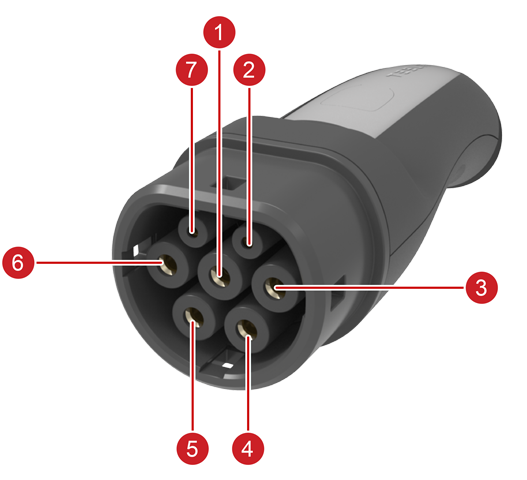
| 1. Ground 2. Prox 3. L1 4. L2 5. L3 6. Neutral 7. Pilot |
| Vehicle Connector |
Enclosurelink
One side of the enclosure is a cable hanger. The front enclosure is made of plastic and is either silver or black. The RESET button is on the other side of the enclosure, as well as nameplate with part and serial numbers. The LEDs indicate the operation and status of Gen 2 Wall Connector. Red blink codes are used for troubleshooting. The cover LED board is connected to the main board using a grey ribbon cable, which can be disconnected on the LED board for easy access.
 |
|---|
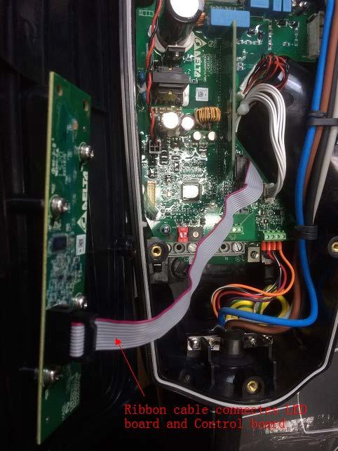 |
| Open Wall Connector with ribbon cable to LED board |
Contactorlink
The contactor remains open until communication has been established and charging is being requested by the vehicle.
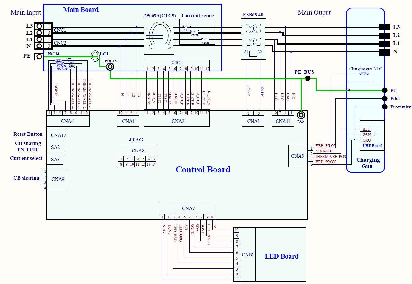
Internal Printed Circuit Board (PCB)link
The main power connections are on the main board with NTCs (Negative Temperature Coefficient Thermistor) on connection points. The main board is located below the Control Board, and is not visible or accessible. It contains main input, NTCs, GFCI (Ground Fault Circuit Interrupter) and current sensors. The control board contains DIP switch, rotary switch, internal power supply, four position terminal block for load sharing communication, and four position terminal block for vehicle connector low voltage circuits such as pilot and proximity.
 |
|---|
| System level schematic of Wall Connector |
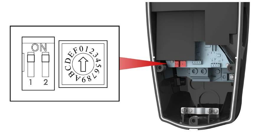
Behaviorlink
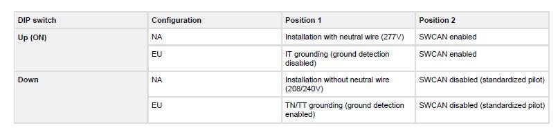
The Gen 2 Wall Connector has a two position DIP switch to configure grid settings and communication, and a rotary switch to configure current capability. Customer facing explanations of these settings are found in the installation manual, and they are also printed on the inside of the Wall Connector. Whenever a setting is changed, the unit should be reset on the reset button, or power should be cycled using the breaker in the installation panel in order to apply the new settings.
 |
|---|
 |
| DIP Switch |
Single-Phase Unit Configurationlink
State of DIP switch position 1 tells the Gen 2 Wall Connector the minimum voltage it should be expecting between its ground terminal and phase terminals. This depends on the transformer configuration, but usually the transformer configuration can be guessed by knowing the line to line voltage of the installation. For example, 240V installations are almost always hooked up to a split-phase transformer that gives roughly 120V from each phase to neutral. By setting DIP switch 1 in the DOWN position the Gen 2 Wall Connector knows it can expect around 120V from phase to ground, and will report a ground fault if the voltage drops significantly below this value. 277V installations are also almost always hooked up to a wye transformer that gives the same voltage, 277V, from L1 to ground. By setting DIP switch 1 in the UP position, the Gen 2 WC will expect around 277V and similarly report a fault if this value deviates. Grounding is required to detect ground faults. There are illustrations and examples of transformer configurations and corresponding voltages in the installation manual.
For the rotary switch, the current configuration is based on a 20% derating of the rated breaker current. The Gen 2 Wall Connector supports breakers rated from 15A to 100A.
Three-Phase Unit Configurationlink
In Europe, the distribution grid voltage is nominal 230V, however grounding schemes vary per country. In the vast majority of Europe power is supplied from a three phase wye transformer with known ground potentials (also known as TN or TT). Therefore, when setting DIP switch 1 to DOWN on the Gen 2 Wall Connector, the ground detection is enabled and expects roughly 230V from L1 to ground terminals. Particularly in Norway the so-called IT grid is quite common. In IT grids, only buildings/consumers are grounded, not the distribution transformer. This means there is an unknown voltage potential from phases to ground when measuring at the consumer site, and therefore the Gen 2 Wall Connector cannot make assumptions with regards to expected ground potential. Therefore, when setting DIP switch 1 UP on a three-phase Wall Connector then ground detection is disabled, and one can only rely on the local installer to properly connect ground wiring. In Norway, one way of recognizing IT grid from a household outlet is by measuring voltage from one live terminal to ground, then the other live terminal to ground using a multimeter. If both voltage readings are between roughly 30 and 200V it is most likely an IT grid. If one reading is close to 0 and the other is close to 230V then it is most likely a TN or TT grid.
The three phase Wall Connector supports breakers rated from 6A to 32A three phase. There is no need for derating since IEC spec breakers are designed to sustain the rated current.
Self-Monitoring and Recoverylink
The Gen 2 Wall Connector has a ground monitoring circuit that continuously checks for the presence of a safe ground connection and automatically recovers from faults. Manual testing and resetting is not required.
Temporary problems such as ground faults or utility power surges are overcome automatically. If a residual current fault occurs that interrupts charging, the Gen 2 Wall Connector automatically tries to clear the fault and reattempt charging.
If the issue is detected again, the Gen 2 Wall Connector waits for 15 minutes before making another charging attempt. This process repeats four times, and if all attempts are unsuccessful, power is removed, and further attempts are halted. A red error light will indicate this on the front panel. To resolve this, it is advised to turn off the Wall Connector using the upstream circuit breaker when the red error light is visible and then power it back on.
The Gen 2 Wall Connector can alternatively be reset when a red error light is encountered using the RESET button. If the Gen 2 Wall Connector is connected to a Tesla vehicle then faults are sent and logged in the vehicle.
Power Outageslink
If a power outage occurs, the Wall Connector automatically resumes charging when power is restored. If the charging cable is plugged into the vehicle when power is restored, the lights blink and the unit does not energize the charging cable for a random period of time extending from 15 seconds to three minutes. This prevents the utility grid from experiencing a large surge when power is restored and allows vehicles to begin drawing current at random times, rather than all at once.
Load Sharinglink
The Wall Connector provides the capability to wire a maximum of four Wall Connectors to a single circuit breaker, giving vehicle owners reassurance that they can charge multiple vehicles at home.
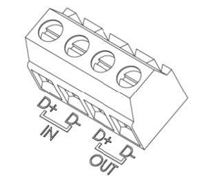
Each Wall Connector has a terminal block as shown in the figure below. D+ is the positive terminal and D- is the negative terminal. Form a daisy-chained network by connecting the cable positive wire between each positive terminal block of the participating Wall Connectors; repeat this procedure for the cable negative wire, which you connect between the negative terminal blocks of the participating Wall Connectors.
 |
|---|
| Load sharing communication terminals |
Designate Wall Connectors as 'paired' by setting the rotary switch to position F. In the load sharing network, only one unit can be designated as the master, and this is determined by setting the rotary switch position. Confirm that the load sharing network is properly installed by observing the LED indicators in the Wall Connector. When starting up the circuit breaker for the first time, Green lights turning ON for 5 seconds indicate a proper installation as follows:
| Green Lights | Yellow Light | Red Light | What it Means |
|---|---|---|---|
| On (top and bottom) | Off | Off | Primary unit |
| On (bottom) | Off | Off | Paired unit |
Control Pilot Signallink
The control pilot (“CP” or “pilot”) signal is generated by the charge equipment (also known as Electric Vehicle Supply Equipment, “EVSE”) to tell the vehicle the maximum AC line current it is allowed to draw. The standardized version of the pilot signal is transmitted as a low voltage (max ± 12V) PWM voltage signal sent through a single wire available in any modern charging cord set. The duty cycle of the PWM tells the vehicle's on-board charger the exact current limit of the supply. This is standardized internationally in IEC 61851-1 and SAE J1772. The vehicle charger includes a switch (called S2) which the vehicle uses to request the charge equipment’s switching device to close, and thus allowing the vehicle to draw current.
Gen 2 Wall Connector allows SWCAN communication over the pilot wire. Whenever CAN packets are transmitted over the pilot wire, the PWM signal is off, and the CAN messages will tell the vehicle about state of supply and voltage/current limits. The pilot wire CAN communication also includes diagnostic information.
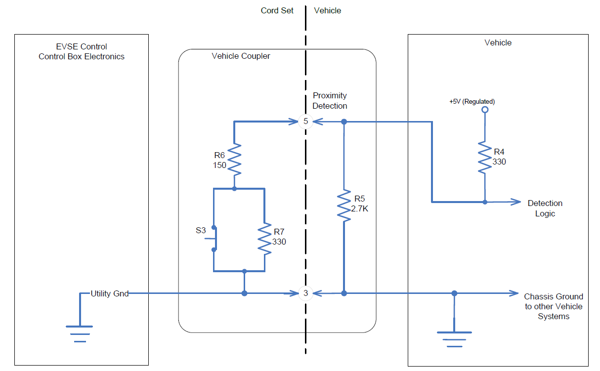
Proximity Circuitlink
The Proximity circuit indicates that a charge cable is physically connected to the vehicle inlet (charge port). The purpose of proximity detection is to initiate the charging sequence, and to prevent movement of the vehicle while a cable is connected.
 |
|---|
| Proximity Circuit, Single-Phase Unit |
In the “not connected” state, the proximity voltage will be approximately 4.5V. In the “connected” (or “latched”) state switch S3 is closed and the proximity voltage is approximately 1.5V. In the “Button Pressed” (or “unlatched”) state, switch S3 is open and the proximity voltage will be 2.8V. The proximity circuit connects to the vehicle where the voltage is monitored and interpreted.
For Gen 2 Wall Connector in three-phase markets, three phase Wall Connector resistor R6 in above diagram is replaced by 220 Ohm. This corresponds to a 32A cable current coding in IEC standards, essentially allowing the Wall Connector to work with third-party vehicles equipped with a Type 2 charge port.
Single Wire CAN (SWCAN)link
SWCAN section in Charge Port.
The SWCAN line charge protocol replaces the traditional pilot-based scheme, enabling use of arbitrary bidirectional data communication between Gen 2 Wall Connectors and vehicles. This allows advanced diagnostics and firmware updating of Wall Connectors in the field. The Wall Connector can switch between standardized pilot and SWCAN operation.
Pilot signal starts at 5% to request SWCAN communication. Pilot EVSE accept switch (S2) is used by the vehicle to accept the 5% duty cycle and thus switch into SWCAN mode, then SWCAN relay is enabled.
The Power Conversion System (PCS) gets current limit through SWCAN message rather than via pilot duty cycle. The vehicle uses the "evseRequest" signal to request contactor closing from Wall Connector.
There are some exceptions to the rules above:
- Wall Connector outputs 5% duty cycle when vehicle sleeps
- Vehicle sleep is detected by no communication and proximity latched
- If DIP position 2 is set to off (“legacy mode”), 5% duty cycle is not used
- If DIP switch position 2 is set to 1 (“SWCAN mode”) and vehicle does not assert EVSE accept, Wall Connector switches to legacy mode automatically after 10sec delay
- Switch-over disabled on Tesla-only Wall Connectors used for Destination Charging
- Used for non-Tesla vehicles for the three-phase Wall Connector
Charging stops and the EVSE opens the contactor within 100ms when any of the following events occur:
- The vehicle requests to stop charging
- The EVSE detects a standard (non-critical) fault
- Prox is unlatched
In addition, charging stops and the EVSE opens contactor immediately when a critical fault occurs or the vehicle communication is lost. Regardless of the shutdown method, SWCAN communications will be maintained until any of the following events occur (at which point the SWCAN relay opens): Prox is disconnected, and communication is lost. The Gen 2 Wall Connector determines that the vehicle is not communicating if it does not receive any CAN messages from the vehicle for 2.5 seconds.
Serviceabilitylink
Alertslink
Available via SWCAN, there are three categories of alerts: warnings, standard faults, and critical faults. Warnings are purely informational, and assist with troubleshooting. Standard faults trigger a controlled shutdown (giving the vehicle time to ramp down current before the Gen 2 WC opens contactors). Critical faults trigger an immediate shutdown and cause the Wall Connector to open contactors immediately (even if current is flowing). These are reserved for faults that require prompt action, such as GFCI trips.
Note
The Gen 2 customer facing Alerts are prefixed with CC\_ to indicate that they
originate from the Wall Connector (CC stands for Charge Connector and is
shared between some charge products like the Gen 2 UMC).
For CC_ alerts, a customer-facing user interface (UI) feature directs the user to the appropriate section in the Owner's Manual.
Toolboxlink
Toolbox article tree supports symptoms (often blink codes) as well as CC_ alerts. Blink codes are connected to alerts in Toolbox, which makes it easy to know what issues can lead to a particular alert or blink code. Alerts are generally more accurate and allow quicker diagnosis, but not always available since the Wall Connector needs to be operative to send alerts to the vehicle. In any case, be sure to check vehicle logs for CC_ alerts when diagnosing Wall Connector issues.