Charge Portlink
Last updated: October 10, 2024
Overviewlink
The charge port assembly is made up of 4 components:
- Charge port door
- High voltage harness including inlet and latch
- Trim piece with LED indicators (located behind the door)
- Charge port Electronic Control Unit (ECU)
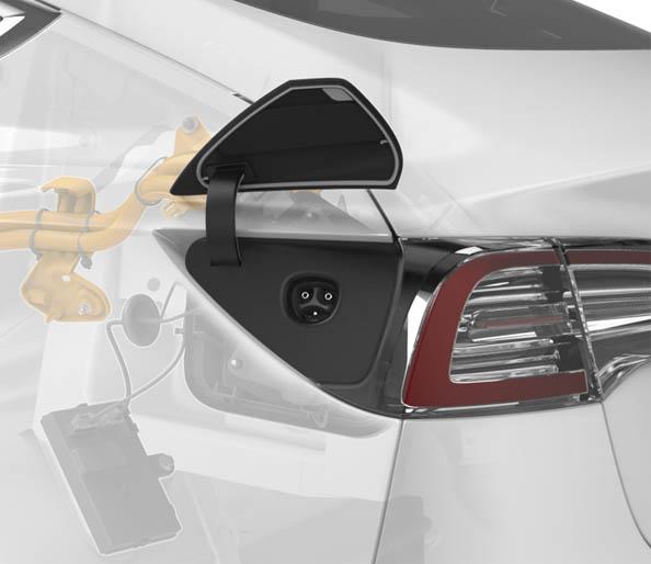
The charge port is located next to the left-hand tail light, which hides the charge inlet when the charge port door is closed.
 |
|---|
| Overview |
The Model 3 charge port door is motorized and opens vertically. The charge port ECU is located in a separate enclosure from the charge port inlet. The charge port ECU has vehicle communication with external charge equipment such as Supercharger, Wall Connector and UMC. The charge port ECU is connected to the High Voltage System (HVS) controller area network (CAN) bus. This means it can communicate with Battery Management System (BMS), Power Conversion System (PCS), and High Voltage Processor (HVP). The High Voltage (HV) charge port harness connects to the Ancillary Bay where power is distributed to the PCS for alternating current (AC) charging and HV battery using fast charge contactors for direct current (DC) charging. The HV harness includes the charge port inlet to avoid bolted HV connections, and the inlet pins are temperature monitored. The charge handle should be 5 - 10 inches (15 - 25 cm) from the charge port door for effective operation of the remote open button.
Charge Port Assemblylink
 |
|---|
|
| Charge Port Assembly, Overview |
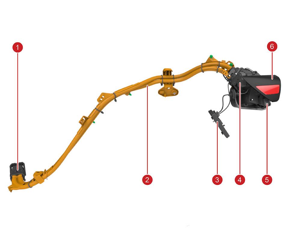
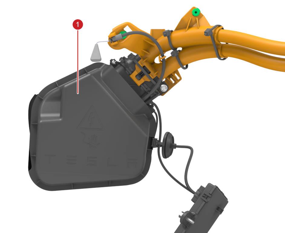
On single-phase charge ports, two HV conductors are used for AC charging (up to 48A or 32A limited by PCS). On three-phase charge ports, two thicker HV conductors are used for DC charging while a separate AC harness connects the AC charging pins to a separate AC charging Ancillary Bay connector that directly routes power to the PCS. The lever assisted Ancillary Bay connector has a charge port high voltage interlock loop (HVIL or CPIL) to make sure that the HV harness connects properly to the Ancillary Bay while charging. The CPIL does not prevent driving nor HV battery power switch closing if in the open position. The plastic guides along the harness mount to the chassis to make sure there is consistent wire routing. The charge port ECU mounts to the wheel arch area with two plastic hooks and a nut.
 |
|---|
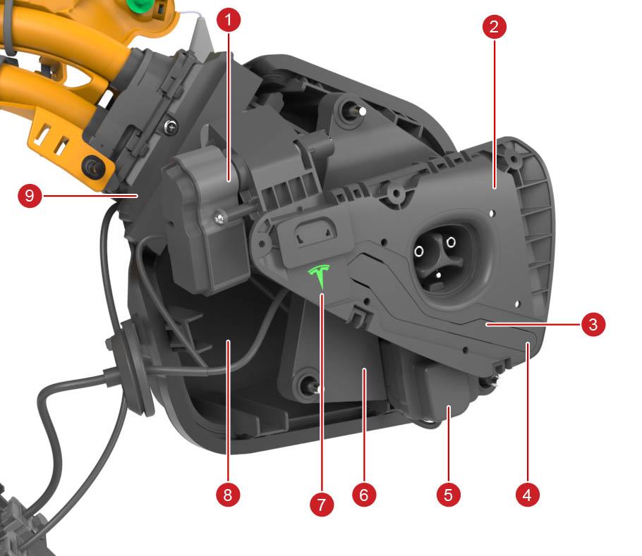
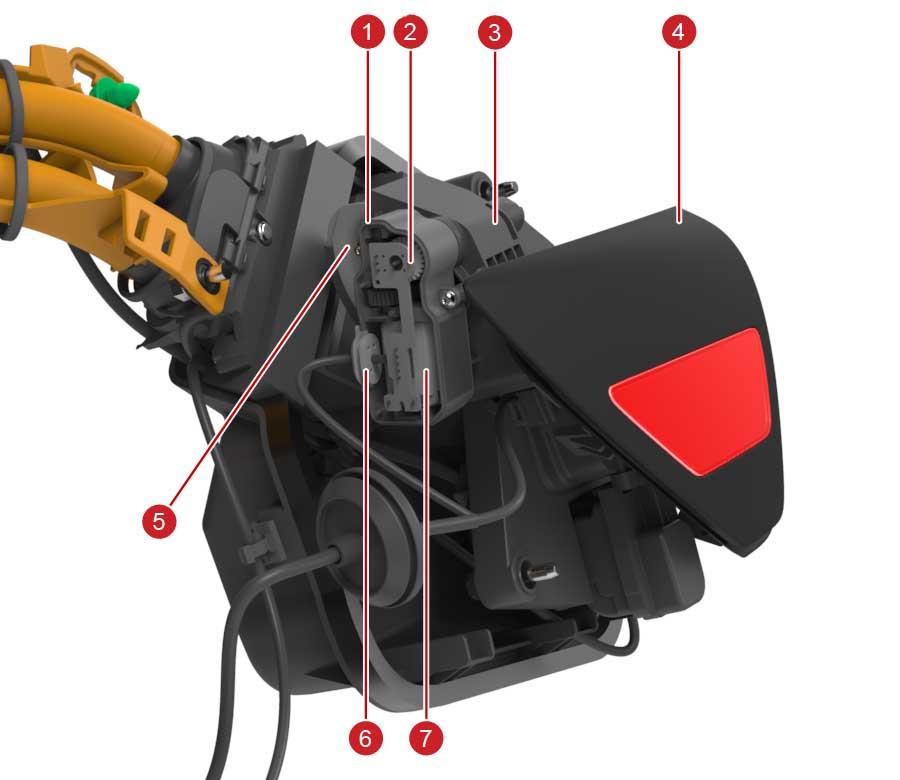
| 1. Door motor (including gears) 2. Charge port trim 3. Trim Printed Circuit Board (PCB) with UHF antenna and inductive sensor 4. Exact coil location for inductive door position detection 5. Latch assembly 6. Plastic carrier (provides additional mechanical support 7. LED-lit Tesla logo (for charge status indication) 8. Closeout panel 9. HV harness including inlet |
| Charge Port (Cosmetic Trim Piece (Black) Hidden) |
The LEDs illuminate a Tesla logo on the upper left side of the cosmetic trim piece.
The flash speed pattern is inversely related to the State Of Charge (SOC). When the SOC is closer to 100% SOC, the flashing is slower, and when the vehicle is done charging, the charge port displays constant green. The flash speed is not related to the line current value or the charge limit setting.
The charge port LED is active when the charge port door is open and one of the following scenarios is true:
- When the vehicle is locked and charging, the green LED stops flashing 2 minutes after vehicle lockout.
- When the vehicle is unlocked and charging, the LED is illuminated during the entire charging session.
- Once the vehicle is fully charged, the charge port LED switches to solid green.
If there is no pilot signal, the LEDs turn off (for example, unplugging a UMC from the wall while connected to vehicle). Each LED color represents a separate condition that must be met as described in the table below:
| LED Color | Charge Port State | Set Conditions |
|---|---|---|
| Solid White | Charging cable can be removed or inserted | The charge port latch is disengaged. |
| Solid Amber | Cable is inserted, but not properly latched | The cable is connected, charge port latch is not engaged, vehicle is trying to engage latch, and vehicle is not charging. |
| Solid Red | Either the charger, charge port, or Electric Vehicle Supply Equipment (EVSE) is not operating as expected | One of the following:
|
| Flashing Green | Charging at expected current | Cable is connected, charge port latch is engaged, and vehicle is actively charging. |
| Flashing Amber | Charging at reduced current | Cable is connected, charge port latch is disengaged, and vehicle is actively charging. |
| Solid Green | Charging is complete | Cable is connected and vehicle is no longer charging. |
| Solid Blue | Pilot is present | Cable is connected and either a pilot signal or fast charger is present. |
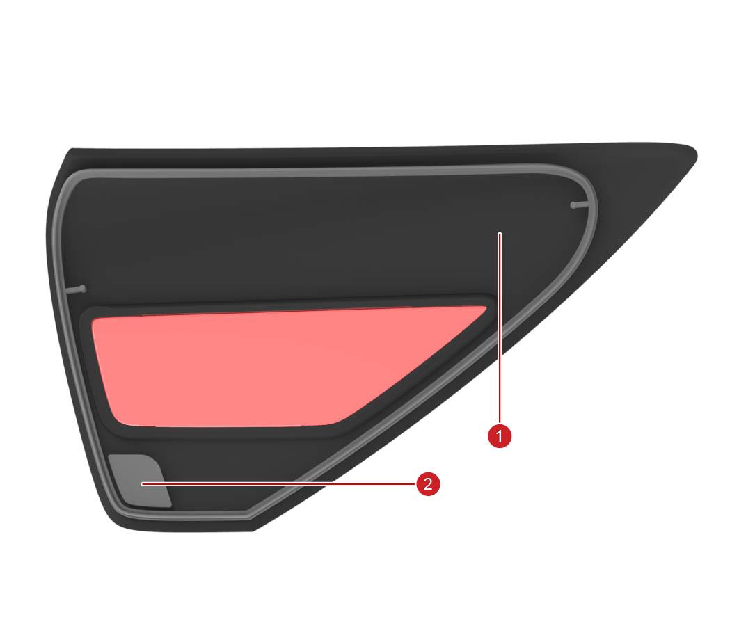
The Trim PCB holds the Ultra High Frequency (UHF) antenna used to detect Radio Frequency (RF) signals from Tesla charge handles and detects the charge port door position. There is an inductive sensor coil on the PCB. The rear of the charge port door has a non-magnetic metallic piece that is sensed by the coil when the door is closed. The charge port ECU relies on relative changes to the inductive door sensor reading to determine that the user pushes the door to open it.
 |
|---|
| 1. Charge port door (rear) 2. Metal piece |
| Trim PCB |
Two non-serviceable low voltage (LV) harnesses connect the charge port ECU to the charge port. The harnesses are covered by the closeout panel. High Voltage (HV) is not exposed below the closeout panel in Model 3 vehicles with cable conductor charge port architecture. High voltage is inside the inlet assembly, and should never be accessed during repairs.
 |
|---|
| 1. Closeout panel |
| Low Voltage Harnesses, With Closeout Panel |
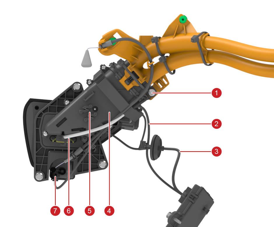 |
|---|
| 1. Chassis ground terminal 2. Inlet and latch LV harness 3. Door and trim LV harness 4. HV harness including inlet 5. Thermistor connectors 6. Inlet signal wire connector (pilot, proximity, ground) 7. 3 pin latch connector |
| Low Voltage Harnesses, Without Closeout Panel |
The picture below shows the routing of the LV harnesses between CP ECU, trim, and inlet. This is specific to North America.
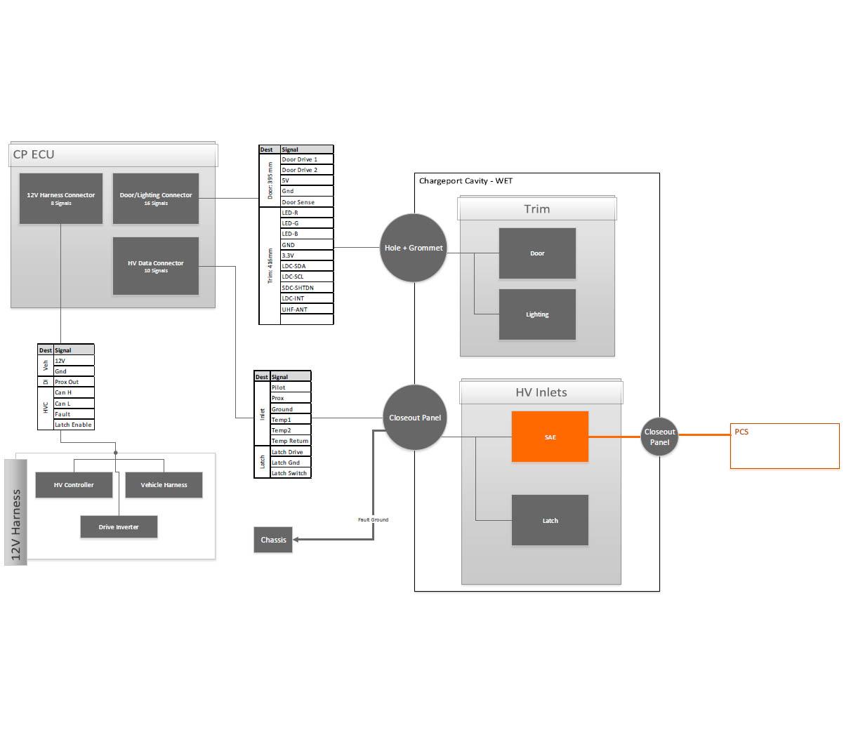 |
|---|
| Routing of LV Harnesses |
Charge Port ECUlink
The charge port ECU controls the following sub-components:
- Charge port door motor
- Charge port door potentiometer
- Charge port latch
- LEDs
- UHF antenna
- Inductive door sensor
- Inlet thermistors
The charge port ECU connects to external charge equipment through pilot and proximity pins in the charge inlet. The charge port ECU is not connected to high voltage power. The charge port ECU enclosure is similar across multiple regions, and can house different internal hardware, resulting in different connector pinout. Therefore, in some cases it may be necessary to verify that the charge port ECU unit matches the vehicle it is being installed in.
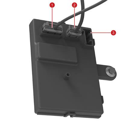 |
|---|
| 1. 24 pin male connector for inlet LV harness (proximity, pilot, thermistors, latch drive, latch sense 2. 16 pin male connector for trim LV harness (LEDs, UHF, door sense, door drive) 3. X096 vehicle interface connector (CAN, power, latch enable signal, HVP fault signal) |
| Charge port ECU |
A 5V source connected to a 330 Ohm resistor supplies the proximity pin. This allows detecting the presence of a charge handle, and the button press state on the handle. For IEC Type 2 and Guobiao charge handles the proximity pin is also used for identifying cable current, so the charge port knows the ampere capacity of the connected cable and can adjust max charge rate accordingly. The charge port also generates a digital proximity signal to the drive inverter which is set when a cable is connected to inhibit drive.
The pilot pin detects the duty cycle of a 1 kHz PWM signal sent from external charge equipment. The duty cycle indicates the max allowable current draw from the charging station. The positive amplitude of the pilot signal indicates vehicle readiness for charging (see Gen 2 UMC Theory of Operation for more details). Additionally, the charge port ECU controls single wire controller area network (SWCAN) communication, which means the charge port ECU has the SWCAN relay and transceiver to communicate with external charging products, such as Supercharger. The charge port sends relevant CAN messages from the SWCAN bus to the HVS bus where the BMS, PCS, and HVP are connected.
The charge port ECU connects to the HVP with two hardware lines:
- The charge port fault line
- Bidirectional active-low signal used by HVP to disallow charging and door opening.
-It is used to prevent HV exposure when, for instance, the fast-charge contactors are welded or assumed welded.
- The signal can also be set low by the charge port when there are risks of HV exposure.
- The fault line immediately stops charging (via hardware and software) if charging is active.
- The charge port latch enable line
- Unidirectional active high signal used by HVP to allow the charge port to drive the latch into disengaged state for cable insertion.
- The charge port cannot drive the latch in either direction if this signal is not active.
Since there is thermal sensing of the charge port inlet power pins, the charge port ECU can read temperatures while charging.
Note
Always consult the circuit diagram and connector reference for the vehicle being diagnosed to confirm which connector is used.
Charge Port Doorlink
The charge port door can open three different ways:
- A request by the user interface (UI)
- Pressing the charge port door
- Pressing the button on a Tesla charge handle
When the charge handle is pressed, a RF signal is sent to the charge port trim PCB UHF antenna. A potentiometer mounted to the door driveshaft senses the door position. The charge port ECU uses the inductive door sensor to determine closed/open/press states. Since the inductive door position sensor is located on the lower right of the charge port door, it is easiest for the inductive sensor to detect door press when pushing at this location. The charge port ECU measures the door motor current for accurate control during door actuation, and stall current detection when reaching fully closed/open positions.
 |
|---|
| 1. Door motor enclosure 2. Potentiometer 3. Charge port trim 4. Door 5. Hinge 6. 5 wire door drive and sense harness 7. Door motor |
| Charge Port With Charge Port Door Motor |
The door motor uses a gear to produce appropriate torque for door actuation. The clutch holds the door in position when it is open without need to drive the motor. This gives it a sturdy feel and makes it somewhat hard to move manually. Normally, customers should not need to manually move the door since it will automatically close 6 seconds after removing a charge handle. If customer moves the door manually when a handle is not connected, the charge port door will close.
Charge Port Inlet Latchlink
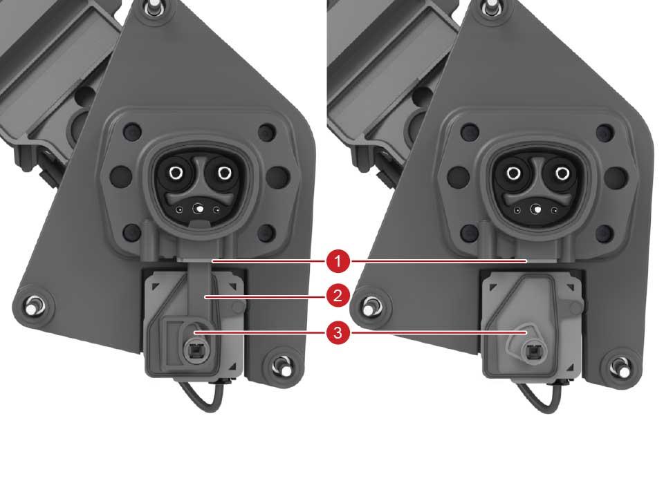
The charge port latch locks the charge handle in place when charging and current is flowing to prevent live disconnect. The charge port latch is actuated by a cam for converting rotational movement into linear movement. The picture on the left shows the latch arm mounted to the cam (without the latch cover), and the picture on the right shows just the cam with the latch arm hidden.
 |
|---|
| 1. Latch seal 2. Latch arm 3. Latch cam |
| Charge Port Inlet With Latch |
The latch uses binary position sensing to report engaged or disengaged. There is no continuous position sensing, which means there is no need for calibration either. The latch needs to be driven by the charge port ECU into engaged and disengaged positions, i.e. there is no spring to force it into engaged state if latch is undriven. The charge port drives the latch at low voltage in the engaged direction every 2 seconds whenever the vehicle is not in Drive and the latch enable hard line is asserted. This is done to confirm that the latch is connected by sensing the latch motor current, since a disconnected latch looks electrically identical to an engaged latch. This can cause a quiet “ticking” noise that is noticeable when listening closely.
Cold Weather Modelink
Single-phase charge ports feature a Cold Weather Mode feature that optimizes the charging experience in cold weather conditions. Cold Weather Mode is entered if the ambient temperature is below 5 degC (41 degF) and exited when the temperature rises above 10 degC (50 degF).
Cold Weather Mode causes the following behavior:
- Charge port latch engages only when current is flowing (for charging or tethering)
- Latch disengages as soon as no current is flowing
- If Scheduled Charging is enabled, the charge port LED will remain white and the latch remain disengaged until the charge session begins
Furthermore, when Cold Weather Mode is active, the customer can request the vehicle to thaw ice from the charge port by preconditioning the vehicle through the Tesla Mobile App and setting the requested cabin temperature to "HI".
Charge Port Latch Manual Release Cablelink
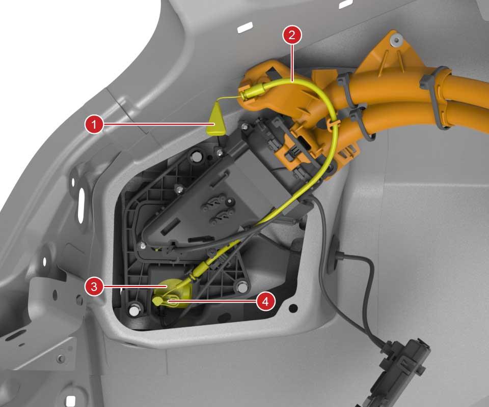
The charge port latch manual release cable is used in emergency situations where the latch or 12V support is not operating as expected while a charge cable is plugged in. This is the only situation the latch release cable should be used. The latch release cable should never be used to disengage the latch to force insert a charge cable. This is because if the latch does not disengage the inlet could be live. The latch release handle is accessible by users from the left-hand trunk area.
 |
|---|
| 1. Trunk latch release handle 2. Latch release cable guide 3. Latch 4. Latch release lever |
| Release Cable |
Serviceabilitylink
Calibrationslink
The latch does not need calibration. The door potentiometer, the inductive door closed sensor, and motor stall current measurements should allow the charge port to operate without need of door calibration.
Diagnosis Methodslink
If the charge port does not operate as expected, it is important to determine if another condition prevents the charge port from operating.
For example, the two hardware signals from HVP can prevent the latch from being driven, or the door from opening, for instance in case a fast charge (FC) contactor has welded or is assumed welded. The FC contactor can be assumed welded if the FC contactor logic harness in the HVC is disconnected or damaged. In this case, alerts from HVP will be present, so generally it is a good idea to resolve all HVP alerts prior to resolving charge port issues.
Additionally, as shown in the charge port LED state table, whenever the BMS is in a faulted state the charge port LED will show red LEDs, so any BMS alerts should be diagnosed before suspecting issues with charge port.
The latch does not have a position sensor, only a closed/open binary state signal.
The door potentiometer gives a position value for the door which can be used for diagnosing charge port door issues.
If the inductive door position sensor is not operating as expected the door may not open when pressing the door, or it may open when not pressing the door. In the former case, the door could be opened by using charge handle or UI. The door will never open when the vehicle is in Drive.
- If the vehicle is in Drive gear, the door will not open using the UI, charge handle button, or press-to-open.
- If the drive rail is enabled but the vehicle is in Park, and either a UI or charge handle open request is received, the front vehicle controller (VCFRONT) will attempt to disable the drive rail. The drive rail will not be disabled with a push-to-open request.
If the latch fails to engage, the vehicle will not allow DC charging, but will be able to AC charge at up to 16A. This is usually sufficient for emergency charging so that the vehicle can drive to a Service Center. If a handle does not latch when inserted in the charge port, inspect the charge port inlet and handle for any signs of obstruction, try a different handle, or very gently wiggle the handle.
Partslink
These are the only parts that can be replaced:
- HV harness which includes the inlet and latch
- HV back cover
- Charge port including door
- Charge port ECU