Autopilot Hardware 4.0link
Last updated: December 17, 2024
Introduction and Overviewlink
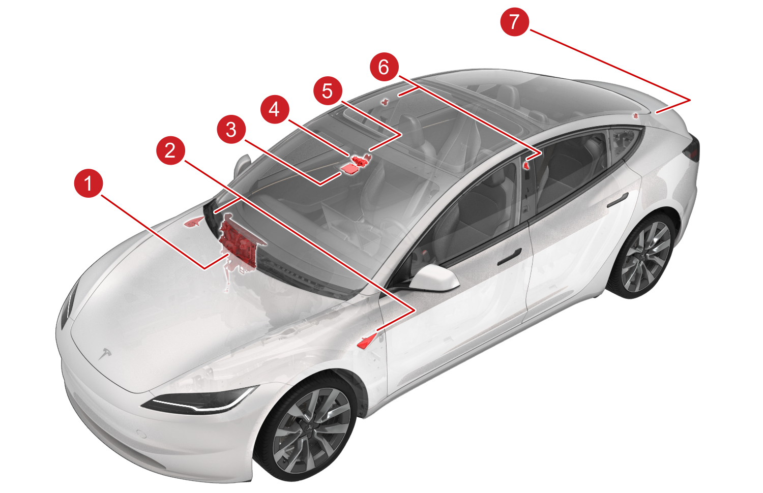
2024+ Model 3 vehicles built after September 2023 are equipped with Driver Assistance hardware generation 4 (HW4) components.
Tip
The Driver Assist Hardware can be identified with the cfg_dashw vehicle configuration. Driver Assistance 4 hardware will have the TESLA_AP4 configuration.
 |
|---|
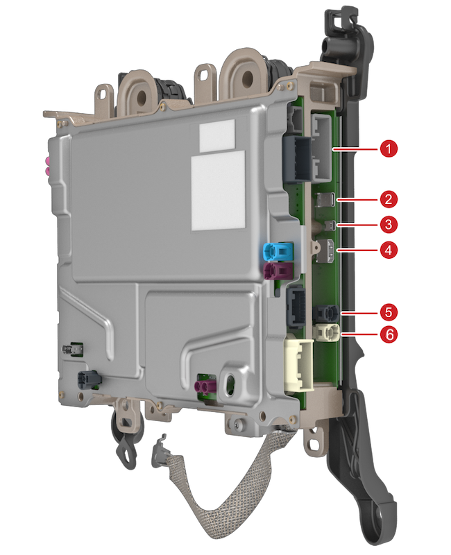
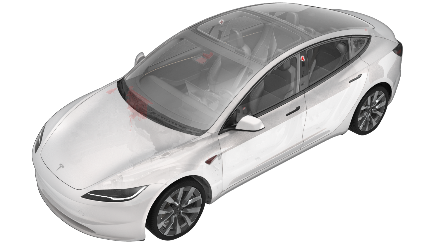
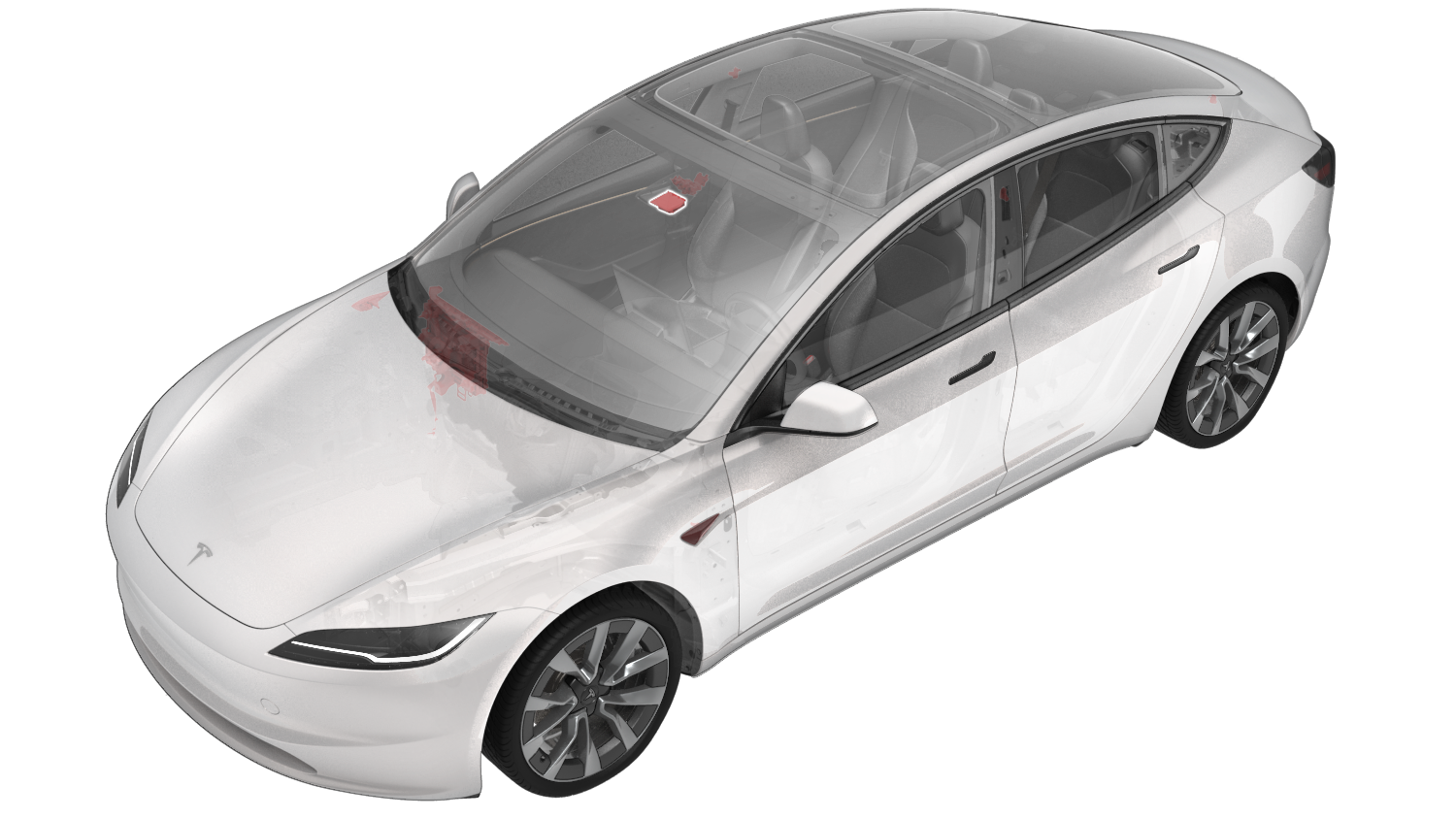
| 1. Driver Assistance Electronic Control Unit (ECU) 2. Side repeater cameras (x2) 3. Global Navigation Satellite System (GNSS) Antenna 4. Forward-facing camera assembly with 2 cameras 5. Cabin camera 6. B-Pillar cameras (x2) 7. Rear-view camera |
| Component Location Overview - Model 3 |
The above listed Driver Assist hardware interfaces with software running on the Driver Assistance electronic control unit (ECU), providing the driver with features like Traffic-Aware Cruise Control (TACC), Autosteer, Autopark, Forward Collision Warning, and Automatic Emergency Braking. Cameras and sensors give the vehicle a 360-degree view, which allows the vehicle to:
- Identify the road layout by detecting lane markings, curbs, barriers, and other obstacles.
- Identify a suitable travel path and speed.
Component Specificationslink
Driver Assistance ECUlink
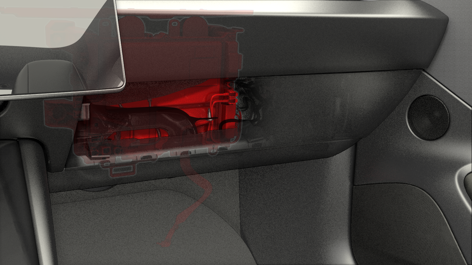
The Driver Assistance ECU (also known as DAS ECU or Autopilot ECU) is part of the car computer and located behind the glove box. Refer to the Infotainment Theory of Operation for additional information about the car computer.
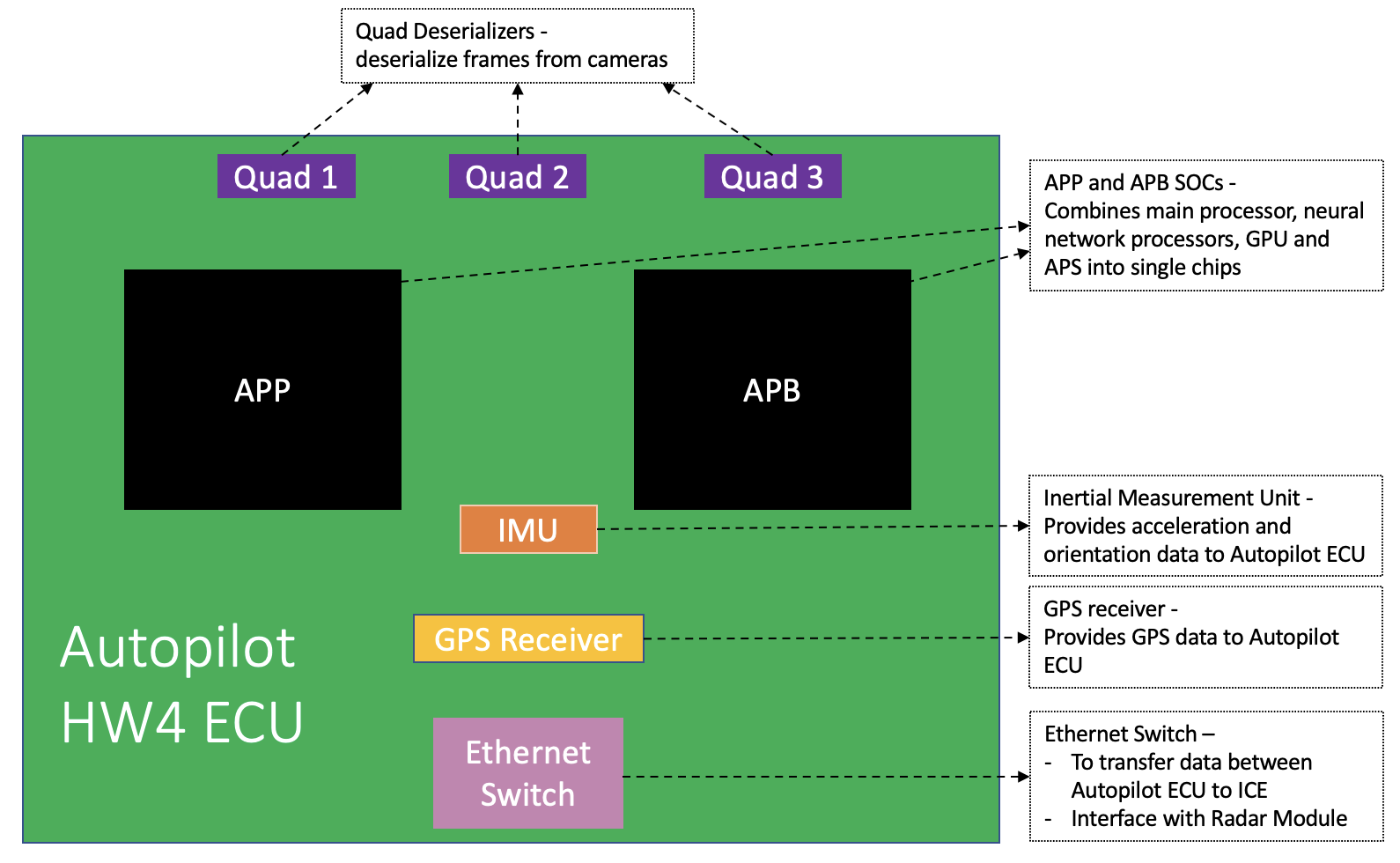
The main functional components of the Driver Assistance ECU:
-
Autopilot Primary Processor (APP)
-
Autopilot Backup Processor (APB)
-
Autopilot Secondary Processor (APS), one each in APP and APB
- GNSS receiver
-
Inertial measurement unit (IMU)
-
Camera inputs
| Common Abbreviation | Definition |
|---|---|
| ESP | Electronic Stability Program Electronic Control Unit (ECU) |
| RCM | Restraints Control Module |
 |
|---|
| Car Computer Location (Left-Hand Drive) |
 |
|---|
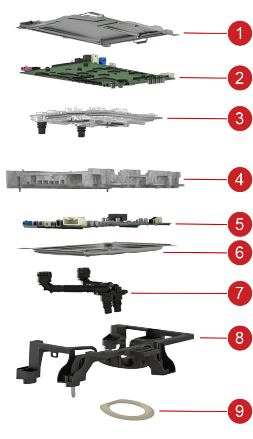
| 1. Stamped sheet metal 2. Infotainment ECU (ICE) 3. Stamped, brazed coldplate 4. Casted frame 5. Autopilot board (DAS ECU) 6. Stamped sheet metal 7. Snap-fit hoses 8. Bracket 9. Seal |
| Car Computer (Exploded View) |
 |
|---|
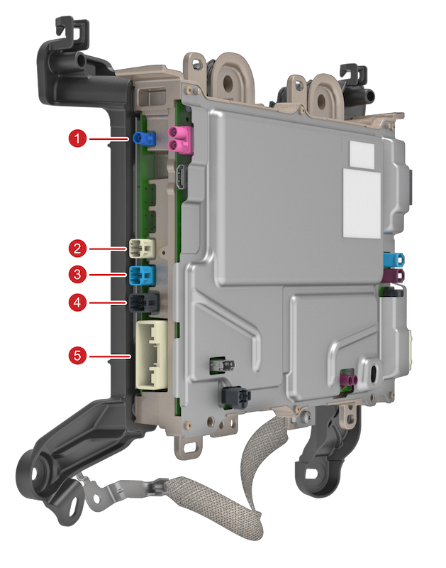
| 1. GNSS Antenna 2. Side repeater cameras (dual connector) 3. Cabin camera and forward-facing fisheye camera (dual connector) 4. Rear-view camera, forward-facing main camera, and B-pillar cameras (quad connector) 5. B-side power (Audio and CAN) |
| Driver Assistance ECU Connectors (Left Side) |
 |
|---|
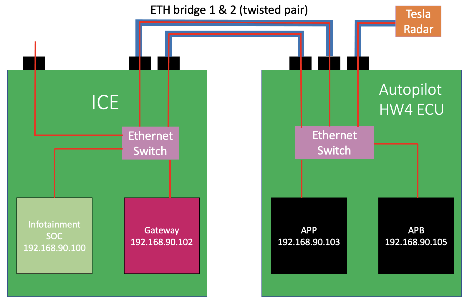
| 1. A-side power 2. Not connected / Diagnostic port 3. Not connected / Diagnostic port 4. Not connected / Diagnostic port 5. Ethernet link 1 to Infotainment board 6. Ethernet link 2 to Infotainment board |
| Driver Assistance ECU Connectors (Right Side) |
 |
|---|
| Functional Units Inside Driver Assistance ECU and Essential Outside Connections |
 |
|---|
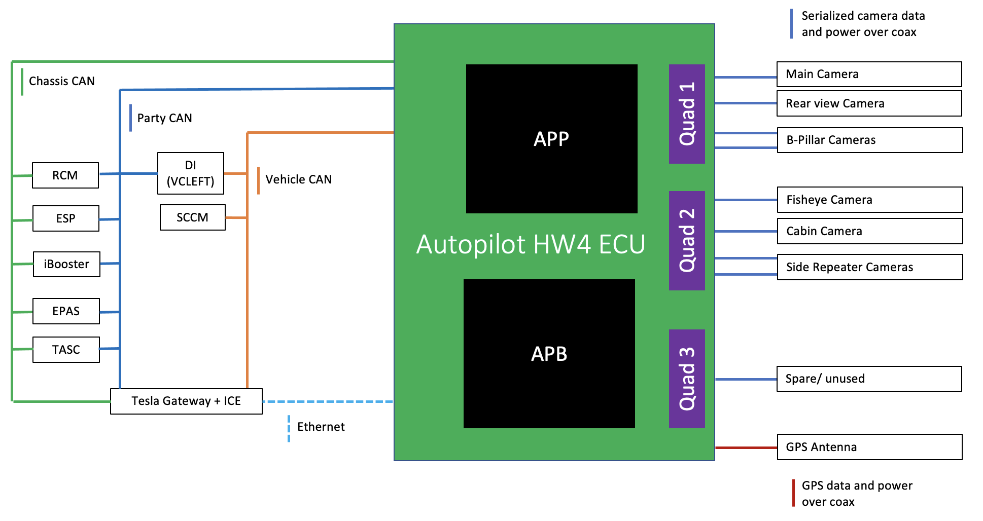
| Driver Assistance ECU Topology |
 |
|---|
| Ethernet Connections |
Driver Assistance ECU Groundinglink
The Driver Assistance ECU's enclosure is grounded to the vehicle chassis ground through one ground strap and bolts from the enclosure to vehicle body in white. This is the primary ground path for the power received from VC Left and VC Right controllers.
When the Driver Assistance ECU is serviced, this ground strap and enclosure bolts should be properly secured before the vehicle or Driver Assistance ECU is powered up. The lack of primary ground path through the ground straps and bolts will force the input current to take the high impedance return via the camera coax cables(if connected) and potentially damage the cable.
APS
- APP & APB and the rear-view camera feedThe speaker is located below the glove box.
The car computer is a part of the battery coolant loop between the chiller and the HV Battery. The location makes sure there is sufficient cooling for the thermally sensitive components on the Autopilot board.
The car computer assembly has a cold plate between the Infotainment and Autopilot board. Sections of the cold plate are raised and in thermal contact with the processors, memory chips, and other electronic components. Coolant entering the car computer exchanges heat with the cold plates, which are in thermal contact with the components allowing to effectively dissipate the heat generated by the processors and regulate temperature.
The Autopilot main processor's operational temperature range is -40°C (-40°F) to 105°C (221°F). As the temperature of the Autopilot processors increases, a higher coolant flow rate is requested. If the Autopilot processor's temperature exceeds the operational temperature range, the processor and autopilot software tasks will shut down, and Autopilot features will not be available.
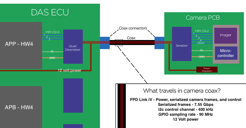 |
|---|
| Camera Data Stream |
All HW4 cameras contain a micro-controller, which initializes the image sensor on the camera. For the Driver Assistance ECU to capture image data from the camera, it needs to initialize the involved hardware components in the following order:
- Initialize the deserializer of the Driver Assistance ECU.
- Initialize the serializer of the camera.
- Verify if the image sensor on the camera has been initialized by the onboard microcontroller.
Deserializer 1
- Port 0: Main camera
- Port 1: Left B-pillar camera
- Port 2: Right B-pillar camera
- Port 3: Rear view camera
Deserializer 2
- Port 0: Right repeater camera
- Port 1: Left repeater camera
- Port 2: Cabin camera
- Port 3: Fisheye camera
Deserializer 3
- Port 0:
- Port 1: Unused
- Port 2: Unused
- Port 3: Unused
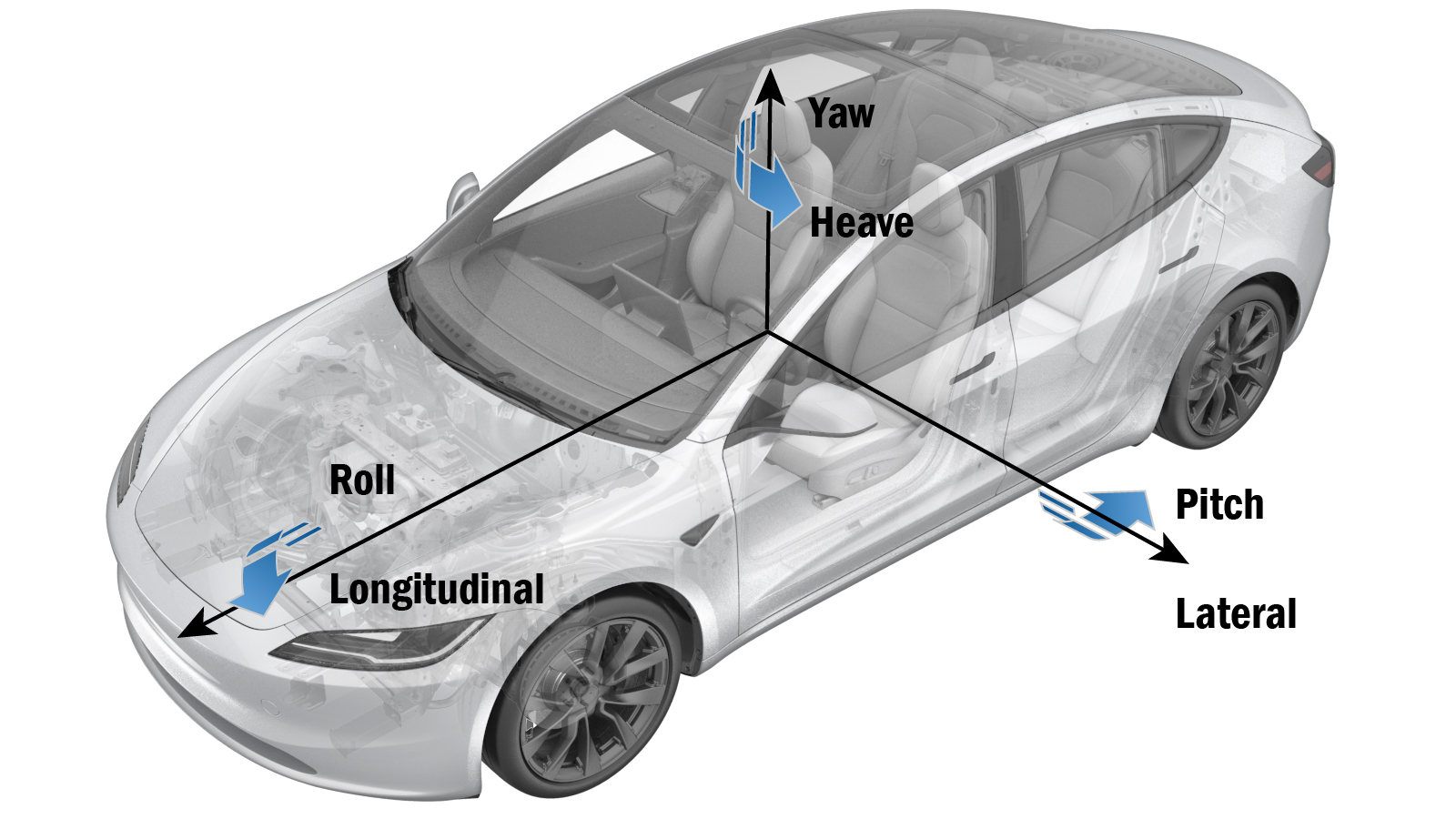 |
|---|
| Camera Pitch, Roll, and Yaw |
Each APS is updated together with the corresponding APE processor package received via Ethernet
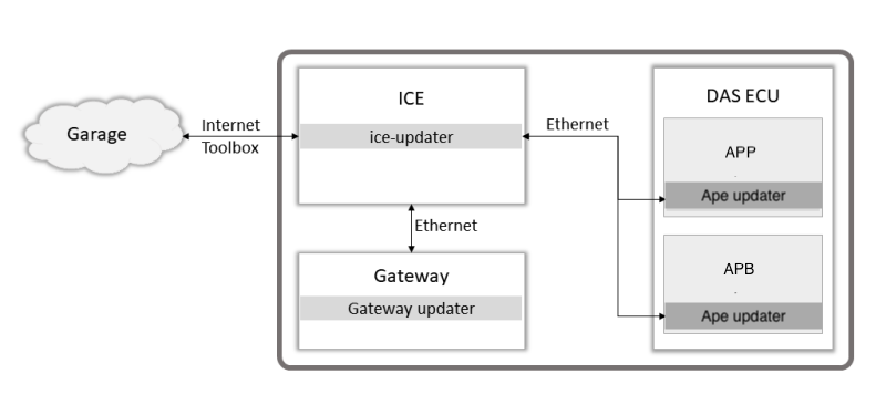 |
|---|
| Simplified DAS Firmware Update |
- Request for additional coolingThe Driver Assistance ECU cannot be replaced as a separate part. The entire car computer must be replaced if there is an internal issue with the DAS ECU.
Cameraslink
Driver Assistance system generation 4 vehicles are manufactured with cameras containing RGGB type camera sensors (color cameras).
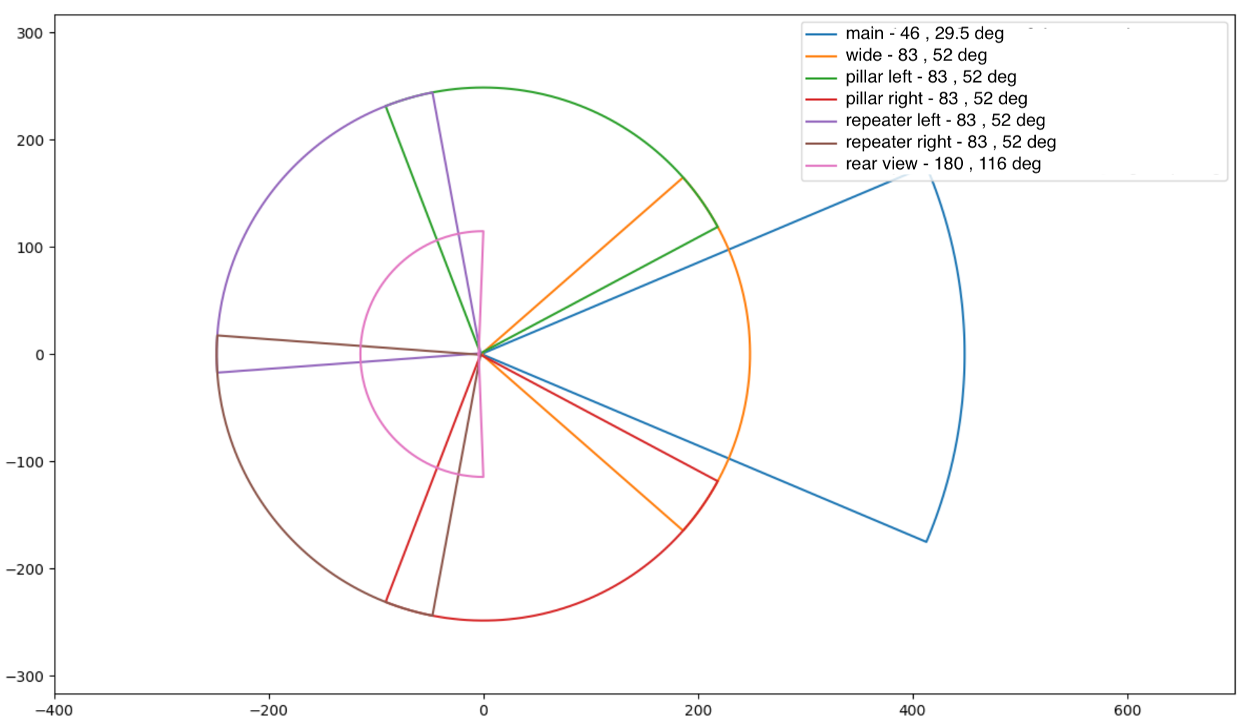 |
|---|
| HW4 Cameras - Field of View |
Each HW4 camera includes a microcontroller on the board that handles tasks like initializing the image sensor. The firmware running on the camera may need to be updated after a camera replacement. To update HW4 camera firmware, conduct a camera ping test utilizing Toolbox or perform a vehicle level software update/reinstall.
Forward Facing Camera Assemblylink
The forward facing camera assembly is mounted on the front windshield and consists of the main and fisheye cameras. Using two different focal lengths gives the system both a wide and deep field of view. This wide field of view allows for detecting objects and environments when planning an appropriate vehicle trajectory or vehicle action. These cameras must be precisely aligned and calibrated. Power to the cameras, control of the cameras, and image data from the cameras is provided through the coaxial wiring connected to the Driver Assistance ECU.
 |
|---|
| 1. Main camera connector 2. Fisheye camera connector |
| Forward Facing Camera Assembly |
Main Cameralink
The main camera is one of the primary cameras used for providing a variety of Autopilot features and Auto High Beam. It can detect vehicles and objects up to 424m when conditions permit.
Specificationslink
- Field of view: 46 degree (horizontal) x 29.5 degree (vertical)
- Temperature range/rating: -40°C to +105°C (-40°F to +221°F)
- Operating voltage: 12V nominal (± 0.5V)
Fisheye Cameralink
The fisheye lens provides a wide field of view. It can detect vehicles and objects up to 205m when conditions permit and is used for providing a variety of Autopilot features along with Auto High Beam and Autowiper functionality.
Specificationslink
- Field of view: 83 degree (horizontal) x 52 degree (vertical)
- Temperature range/rating: -40°C to +105°C (-40°F to +221°F)
- Operating voltage: 12V nominal (± 0.5V)
Camera pitch verification service procedure is a method to approximate the camera pitch value without driving the vehicle to complete calibration. The pitch value approximation using the camera pitch verification procedure is not as accurate as the calibration derived from driving the vehicle but allows service to quickly verify that the camera pitch is roughly within the specifications and has the best chance to calibrate successfully when the vehicle is driven.
Therefore, whenever the forward facing camera assembly, or any component that contacts it, is physically adjusted or removed from the vehicle, camera pitch verification procedure is recommended to be performed. Refer to the Service Manual on how to perform this procedure. If the camera's pitch is approximated to be out of specification, it can be corrected with an adjustment screw next to the rear-view mirror. The vehicle then needs to be driven to complete calibration.
If the forward-facing camera is not operating as expected, inspect the connectors and coaxial cable from the camera to the Driver Assistance ECU.
An alert for each camera will be sent from the Driver Assistance ECU when:
- The ECU is unable to initialize cameras
- The camera image stream is interrupted
- An incorrect camera type is installed
- Main or narrow camera pitch is out of spec
Potential points of failure:
- Camera coaxial cable and connectors
- Camera assembly
- Driver Assistance ECU
The forward-facing camera(s) are replaceable as an assembly, it is not advised to replace the cameras individually as the cameras in the assembly are aligned to a specification at the manufacturer.
Windshield Camera Fan Assemblylink
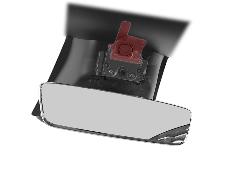
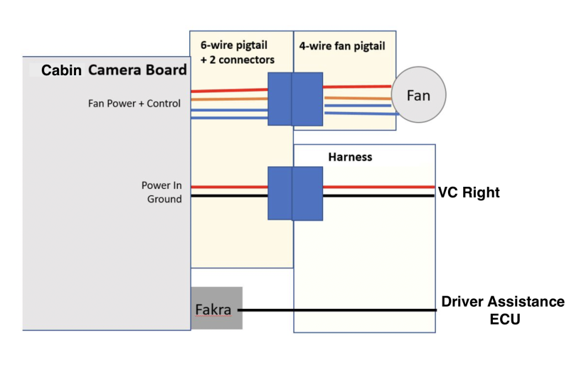
The windshield camera fan assembly is situated above the rear-view mirror and is directly mounted to the windshield bracket. The purpose of the fan is to improve air flow in the forward-facing camera's field of view region to help prevent and/or clear any condensation formed on the inside of the windshield. The windshield camera fan assembly receives power and control from the cabin camera module, which has a dedicated microprocessor for fan control. The power to run the fan is received by cabin camera module from the VCRIGHT controller. The cabin camera module has 1 coaxial connector and a six-wire pig tail with 2 connectors.
Fan control:
- Driver Assistance ECU receives and uses the data from the heating, ventilation, and air conditioning (HVAC) (Blower speed and Mode) system, cabin camera (temperature), and forward-facing camera (temperature and vision status) to calculate fan demand.
- Fan demand data is sent over the cabin camera coaxial cable to the microcontroller on the cabin camera module using i2C communication protocol.
- The microprocessor on the cabin camera module controls the fan power status and speed based on the fan demand it receives from Driver Assistance ECU.
 |
|---|
| Windshield Camera Fan Location |
 |
|---|
| Cabin Camera Module Topology |
Diagnostics, Serviceability, and Calibrationlink
If the windshield camera fan assembly is not operating as expected, inspect the connectors and wiring from the cabin camera module to the Driver Assistance ECU, the cabin camera module to the fan assembly, and the cabin camera module to the VCRIGHT. Inspect for any physical blockage preventing the fan operation like a trapped harness or dirt/debris.
Potential points of failure:
- Wiring and connectors
- Cabin camera module
- Fan assembly
- Driver Assistance ECU
- VCRIGHT
Cabin Camera with Infrared sensorlink
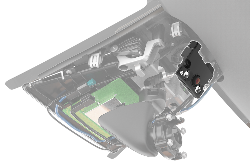
The cabin camera is situated above the rear-view mirror with an overview of the cabin. Power to the camera, control of the camera, and image data from the cabin camera are provided through the coaxial wiring connected to the Driver Assistance ECU.
The cabin camera module comes equipped with 2 infrared (IR) light emitting diodes (LEDs), which illuminate the cabin. The camera sensor is both natural light and infrared sensitive, allowing the camera to have visibility in all lighting conditions. The cabin camera module housing and the beauty cover (plastic trim piece over rear-view mirror) are both infrared transparent and the LEDs are internal to the module (not visible externally). The camera uses a dual band pass RGB-IR filter to maximize different lighting conditions during the day or night for higher quality images.
Cabin camera is being used for driver monitoring only on certain vehicle configurations and regions. If the system detects that the driver is inattentive, they are alerted with an audible chime and a visual warning is displayed on the screen reminding them to place hands on the steering wheel.
Specificationslink
- Field of view: 150 degree (horizontal)
-
IR LED wavelength: 940nm
-
Operating voltage: 12V nominal (± 0.5V)
 |
|---|
| Cabin Camera Location (Model S Shown, other Models in Similar Location) |
 |
|---|
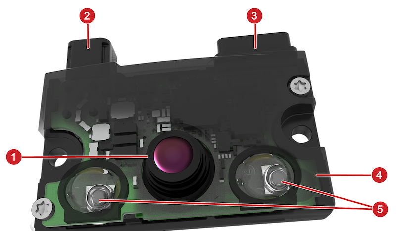
| 1. Camera lens 2. Camera coaxial connector 3. Pigtail with connectors for windshield camera fan and VCRIGHT
5. Infrared LEDs |
| Cabin Camera Module |
Side Repeater Cameraslink
The side repeater lamp assemblies mounted on the front fenders include a camera. These cameras face in a rearward direction and are able to monitor rear blind spots on both sides of the vehicle. Power to the cameras, control of the cameras, and image data from the cameras are provided through the coaxial wiring connected to the Driver Assistance ECU. The connection for the side repeater LED is separate from the camera wiring.
The side repeater camera is a module by itself and is mounted to the side repeater lamp assembly using 2 screws. This allows the camera to be removed and replaced independent of the side repeater lamp assembly.
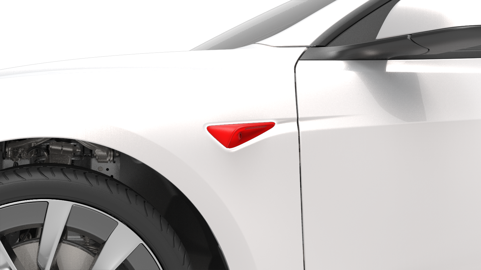 |
|---|
| Side Repeater Camera Location |
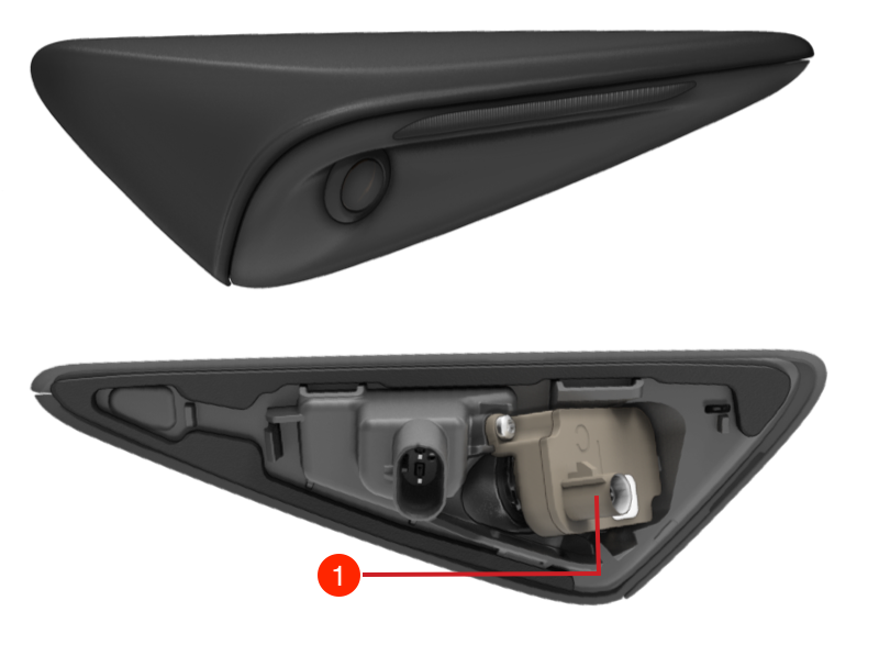 |
|---|
| 1. Camera coaxial connector |
| Side Repeater Camera |
Specificationslink
- Field of view: 83 degree (horizontal) x 52 degree (vertical)
- Temperature range / rating: -40°C to +105°C (-40°F to +221°F)
- Operating voltage: 12V nominal (± 0.5V)
Diagnostics, Serviceability, and Calibrationlink
If the side repeater camera is not operating as expected, inspect connectors and the coaxial cable from the camera to the Driver Assistance ECU.
The Driver Assistance ECU sets alerts for the items listed below when:
- The ECU is unable to initialize cameras.
- The camera image stream is interrupted.
- An incorrect camera type is installed.
Potential points of failure:
- Coaxial cable and connectors
- Camera
- Driver Assistance ECU
The side repeater camera can be replaced independently of the side repeater lamp assembly. After camera replacement, calibration will occur during driving.
Note
The side repeater camera assembly is different from previous versions and not backwards compatible with other Tesla vehicle models.
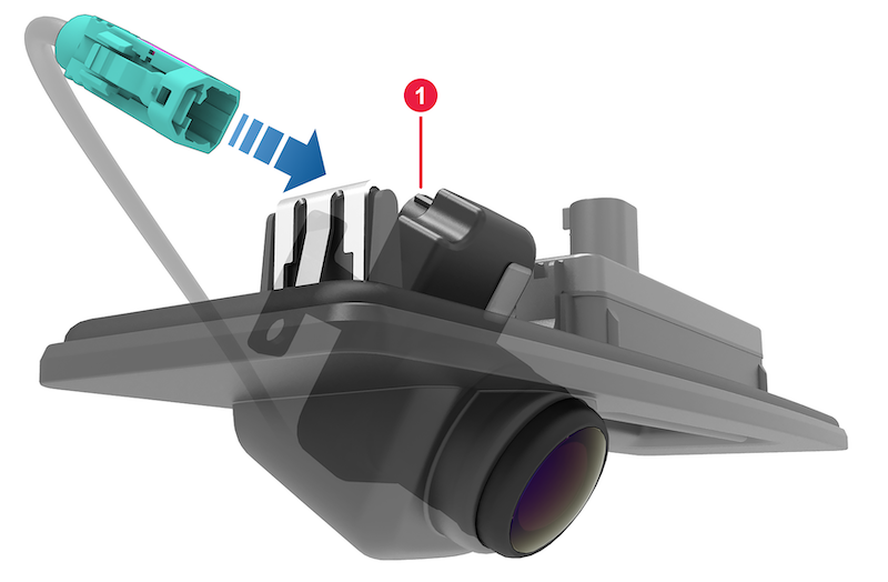
B-Pillar Cameralink
The B-Pillar cameras provide image data for each side and the front corners of the vehicle, which aid in detecting vehicles entering the vehicle's lane on a highway and cross traffic at intersections. The cameras are embedded into each B-Pillar behind the applique. Power to the camera, control of the camera, and image data from the cameras are provided through the coaxial wiring connected to the Driver Assistance ECU.
A portion of the B-Pillar applique glass around the camera field of view is equipped with a resistive type heater. The heater is either powered by VCLEFT or VCRIGHT depending on the side installed and will help in clearing ice and condensation built up in the camera field of view. This feature is not currently supported and will be activated through a future firmware update.
 |
|---|
| B-Pillar Camera Location |
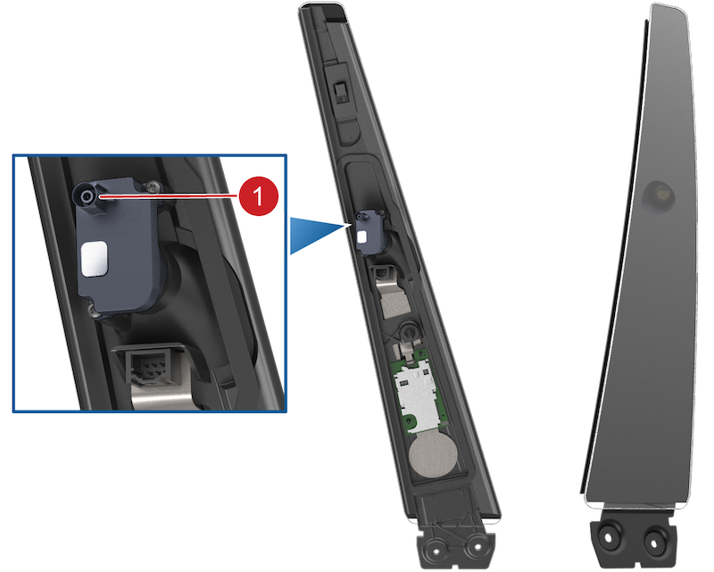 |
|---|
| 1. Camera coaxial connector |
| B-Pillar Camera (Model X B-Pillar Applique Shown, other Models Similar) |
Specificationslink
- Field of view: 83 degree (horizontal) x 52 degree (vertical)
- Temperature range/rating: -40°C to +105°C (-40°F to +221°F)
- Operating voltage: 12V nominal (± 0.5V)
Diagnostics, Serviceability, and Calibrationlink
If the B-pillar camera is not operating as expected, inspect connectors and the coaxial cable from the camera to the Driver Assistance ECU. An alert for each camera will be set by the Driver Assistance ECU when:
- The ECU is unable to initialize cameras.
- The camera image stream is interrupted.
- An incorrect camera type is installed.
Potential points of failure:
- Camera coaxial cable and connectors
- B-pillar camera
- Driver Assistance ECU
The B-Pillar camera can be separated from the B-Pillar applique and is independently serviceable. After camera replacement, a calibration will occur during drive.
Rear-View Cameralink
The rear-view camera has a wide-angle lens, which enables the driver to view a large area behind the vehicle. The camera is connected to the Driver Assistance ECU and receives power from it. The image stream received is split for DAS ECU internal use and forwarded to the Infotainment ECU via Ethernet. This generation of DAS ECU does not utilize a coaxial jumper cable for the rear-view camera.
 |
|---|
| 1. Camera coaxial connector |
| Rear-View Camera with Connector |
Diagnostics, Serviceability, and Calibrationlink
If the rear-view camera is not operating as expected, inspect the connectors and wiring from the camera to the Driver Assistance ECU, and from the Driver Assistance ECU to the Infotainment ECU. Confirm there are no issues with the touchscreen displaying the camera image.
Potential points of failure:
- Wiring and connectors
-
Camera
-
Infotainment and Connectivity ECU (ICE)
-
Driver Assistance ECU
The rear-view camera assembly is individually replaceable.
Autopilot HW4 Model 3 and Model Y vehicles do not come equipped with a radar module. These vehicles rely on camera vision and neural net processing to deliver Autopilot, Full self-driving beta and certain other active safety features.
GNSS / GPS Antenna and Modulelink
The Global Navigation Satellite System (GNSS) antenna is located above the rear-view mirror under the forward camera's glare shield. The antenna board comes equipped with a metal reflector on the bottom side (towards the vehicle cabin) to provide electromagnetic interference (EMI) shielding from other nearby components.
 |
|---|
| GNSS Antenna Location |
The GNSS receiver is integrated into the Driver Assistance ECU. It uses a coaxial cable to power the antenna assembly and to receive Radio Frequency (RF) signals from the Low Noise Amplifier (LNA) built into the antenna assembly . The Autopilot secondary processor Autopilot Primary (APP) configures and controls the GNSS receiver. When the Driver Assistance ECU is not operational, GNSS is not available for all other consumers. To decrease the time until the location is calculated (GNSS fix), portions of the receiver module are always powered, even when the vehicle is asleep, to retain state.
The GNSS receiver is able to use Global Navigation Satellite System (GNSS) signals from the GPS, GLONASS, Galileo, or Beidou satellite constellations simultaneously (depending on the vehicle's region) and is capable of extracting carrier phase measurements from each available signal. The GNSS receiver transfers received satellite measurement observations to the Drive Assistance ECU processor, which uses a software Positioning Engine to estimate the location of the vehicle using the carrier phase measurements generated by the receiver. The Positioning Engine is enabled to receive two frequency bands from each satellite constellation - L1 and L5. Additionally, the Positioning Engine receives data from the Inertial Measurement Unit (IMU) and the vehicle’s wheel speed sensors to augment the GNSS measurements. The IMU uses gyroscopes and accelerators to estimate the motion and orientation change of the vehicle while wheel speed sensors detect incremental motion of the vehicle's tires. Through a process known as sensor fusion, the Positioning Engine combines data from the GNSS system, the IMU, and the wheel speed sensors to track the position of the vehicle. The process produces a solution that is more accurate than can be generated from GNSS measurements alone and can continue to track the vehicle even when GNSS signals are not available for short periods of time. This improves the accuracy and sensitivity of the position estimates used by features like Autosteer and Smart Summon.
If there is limited satellite reception (like in tunnels or underground parking), the Positioning Engine will attempt to estimate the position with just the wheel speed and IMU data. This is called "dead-reckoning", and while accurate over short distances, the estimate will diverge with distance traveled by the vehicle until a satellite signal is regained. Generally, the Positioning Engine needs a minimum of four satellites in view from a single constellation to generate a GNSS fix and regain a fully fused solution that will not drift with time.
Note
While GPS is technically just one of the satellite constellations, GPS is widely used as a synonym for the GNSS in general.
Specificationslink
-
GNSS antenna supply voltage: 5V nominal (3-5V range)
-
Operating temperature GNSS receiver: -40°C - 105°C (-40°F - 221°F)
- Operating temperature GNSS antenna: -40°C - 105°C (-40°F - 221°F)
Diagnostics, Serviceability, and Calibrationlink
If GNSS is not operating as expected, make sure that the Driver Assistance ECU is operational. Inspect the coaxial connectors and wiring from the Driver Assistance ECU to the GNSS antenna. The location information is shared with the User Interface (UI) over Ethernet, so while an issue with the connection does not affect the GNSS system, it will affect any features on the UI or other systems that depend on localization data. An alert will be set by the Driver Assistance ECU when:
- No or invalid data was received from the GNSS receiver.
- GNSS antenna is disconnected.
- GNSS receiver was reset.
- Voltage to the GNSS antenna is not as expected.
- Fusion mode status changes.
Potential points of failure:
- GNSS coaxial wiring and connectors
- GNSS antenna
- EMI from cameras and camera harnesses leak into the GNSS antenna and degrade the quality of the received signals
- Driver Assistance ECU
The GNSS antenna and the coaxial wiring can be replaced separately. The GNSS receiver is part of the Driver Assistance ECU and can only be replaced as a whole. After replacing either part, GNSS calibration is not required.
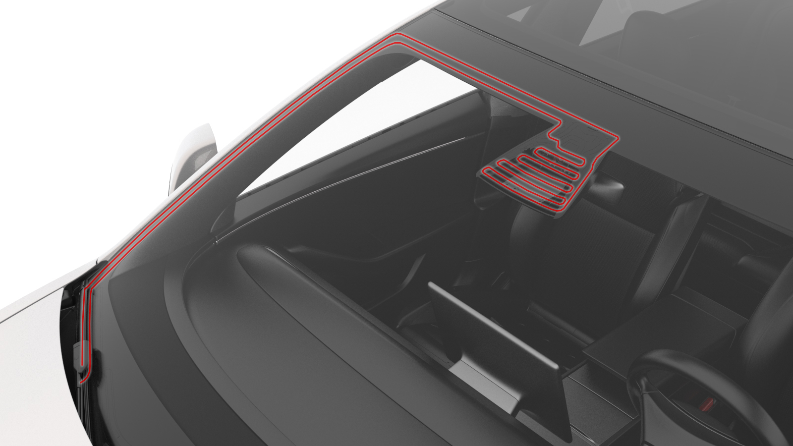
Camera Heater Gridlink
 |
|---|
| Camera Heater Grid Location |
The camera heater grid is controlled by the Driver Assistance ECU but electrically driven by the Front Vehicle Controller (VCFRONT) and is used to clear the front-facing camera view of condensation, snow, or ice.
The heater grid will be activated when defrost is requested or when Autopilot anticipates ice or condensation based on occlusions and environmental conditions. The heater grid will never operate above +30°C or +86°F ambient temperature.
- Windshield temperature is above the activation temperature (+6°C or +44.6°F).
- Windshield defrost and preconditioning are off.
Diagnostics, Serviceability, and Calibrationlink
If the heater grid is not working as expected, make sure to inspect the wiring to it. Confirm the above enable conditions are met and that the ambient and windshield temperature sensors (if present) are reporting correct values.
An alert will be set by the Driver Assistance ECU when a short or open circuit is detected in the camera heater grid. Potential points of failure:
- Wiring and connectors
- Ambient temperature sensor
- Temperature sensor near windshield
- Driver Assistance ECU
The camera heater grid is part of the windshield and can only be replaced as a whole. After replacing the windshield, camera pitch angle verification is required. The camera heater grid is part of the windshield and can only be replaced as a whole. After replacing the windshield, camera pitch angle verification is required.
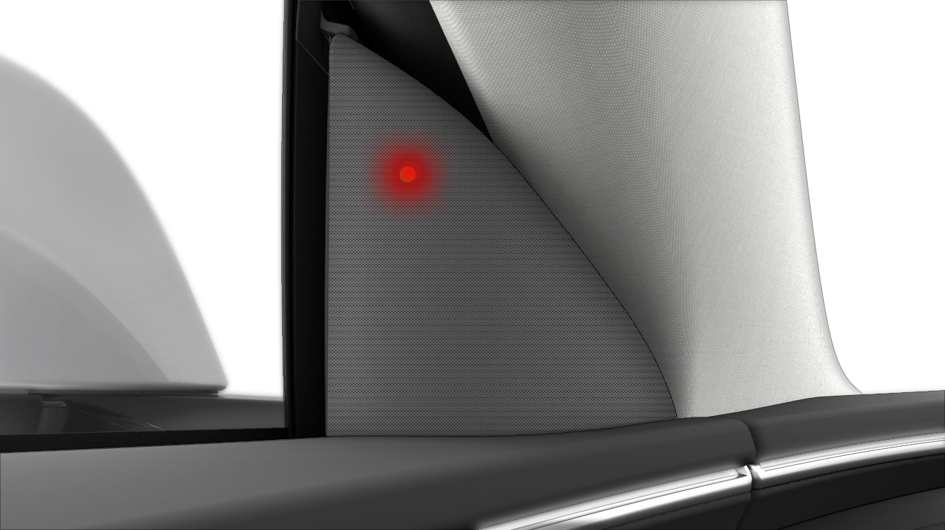
Blind Spot Indicatorlink
 |
|---|
| Blind Spot Indicator Location |
 |
|---|
| Blind Spot Indicator with Connector |
The blind spot indicators (BSI) are integrated into the front door tweeters, and electrically driven by the left vehicle controller (VCLEFT) or right vehicle controller (VCRIGHT) depending on its location. VC will blink the corresponding BSI at different frequencies upon requests from DAS through Controller Area Network (CAN), to alert driver that there is a vehicle detected in or approaching the blind spot.
- User can turn blind spot indicator on or off through a UI switch.
Specificationslink
- Temperature range/rating: -40°C to +85°C (-40°F to +185°F)
- Voltage: Regulated 3.4V ± 5%
Diagnostics, Serviceability, and Calibrationlink
If blind spot indicator is not working as expected, make sure to inspect the wiring to it.
Vehicle Controller and Driver Assistance ECU will trigger alerts when:
- An open circuit or a short to ground is detected.
- Blind spot indicator is unavailable for DAS to use
The blind spot indicator can be replaced separately. Calibration is not required after replacement.
Driver Assist Featureslink
Note
Not all Driver Assist features are available in every country. See the local Owner's Manual on Feature Availability and if there are different conditions for activation.
Traffic Aware Cruise Control (TACC)link
| Sensors and Data Used | Forward facing cameras:
|
| Speed limitations | Minimum speed for activation:
|
TACC maintains a driving set speed in the same way as standard cruise control but can also adjust the speed of the vehicle based on the distance to other vehicles in the same or adjacent lane (Undertake Assist). TACC will adjust the speed based on map data and during manual lane changes, reduce speed to target lane vehicles. TACC can be activated once traveling faster than 5 mph or 8 km/h, unless certain conditions allow an activation at even lower speeds. At standstill, TACC will activate if a vehicle is at least 5 feet (150 cm) detected ahead.
TACC is enabled by pressing the right scroll wheel on the steering wheel once, if configured in UI settings. TACC will set the detected speed limit (see Speed Assist) or the current driving speed as cruise speed, whichever is greater. When a speed limit is detected and shown in the cruise control symbol, this speed (+ possible speed warning offset) will be set as cruise speed.
If TACC is active, speed can be increased or decreased by moving the right scroll wheel up or down, or by using the ± icons on the UI, in 1 km/h (1 mph) or 5 km/h (5 mph) increments. To adjust cruise speed to a new speed limit determined by Speed Assist the driver can cancel and re-engage TACC or touch the speed limit sign on the UI. Cruise can be canceled by the driver by pressing the brake or the right scroll wheel.
Cruise will not be available when:
- The speed drops below 5 mph / 8 km/h and no lead vehicle detected.
- Driving speed exceeds 90 mph or 150 km/h.
- The driver's seat belt is unbuckled.
- The door is opened.
- The trunk or frunk is opened.
The driver can choose 7 different following distances via the UI touch buttons.
The distance will increase when the wiper activity suggests poor road conditions or ambient temperature is low (< 3°C / 38°F).
Diagnostic Informationlink
If Traffic Aware Cruise Control does not become available, check:
- If a right scroll wheel press is logged.
If Traffic-Aware cruise control does not work as expected or aborts, check:
- If vehicle has been driven under mentioned limitations.
- For cruise control related alerts.
Curve Speed Adaptationlink
Curve Speed Adaptation (CSA) is a feature of TACC. CSA reduces the vehicle's speed in anticipation of upcoming curves or bends in the road. This is done by temporarily slowing the vehicle down to an appropriate speed.
CSA activates when:
- Taking a highway exit.
- Predicted lateral acceleration along the most probable path reaches a certain threshold (uses either local navigation data or online Tesla maps).
- Current measured lateral acceleration of the vehicle reaches a certain threshold.
Fleet Speedslink
Fleet Speeds helps to slow the vehicle down to an appropriate speed when entering and exiting highways or driving on interchanges with Autosteer or TACC active. Speed will be reduced to the average speed that other Tesla vehicles drove on that road section but will not exceed the speed limit set by the driver. The set speed on the UI will be reduced in increments of 5 mph or 10 km/h rounded up to match the average Fleet Speed, though speed will not drop below 25 mph or 40 km/h. As long as Fleet Speeds is active, an animation of the circle around the set speed value will be shown on the UI. Drivers can override the new speed with the accelerator or brake pedal (as for TACC in general) if they consider it inappropriate.
Entering highways (on-ramp):
- Fleet Speeds might slow the vehicle down (depending on current set speed).
- Speed can change dynamically similar to how the fleet reported speed changes.
- Once the vehicle is on the highway, it will accelerate back to the previous set speed.
Highway interchanges:
- Fleet Speeds might slow the vehicle down (depending on current set speed).
- Speed can change dynamically similar to how the fleet reported speed changes.
- Once the vehicle is in targeted space, it will accelerate back to the previous set speed.
Exiting highways (off-ramp):
- Fleet Speeds might slow the vehicle down (depending on current set speed).
-
Speed can change dynamically similar to how the fleet reported speed changes.
-
Upon leaving the exit, Fleet Speeds will be actively controlling the speed for at least 100 m (110 yd) up to 2 km (1.2 mi) until the next road speed limit is detected.
- Fleet Speeds becomes inactive after either the new detected speed limit is set, or the previous set speed is restored.
Diagnostic Informationlink
Fleet Speeds cannot be deactivated but depends on the availability on map data of the fleet's average speed. If Fleet Speeds does not work as expected or at all, check for incorrect localization to nearby roads resulting in incorrect speed adjustments.
Overtake Accelerationlink
When Traffic Aware Cruise Control is active, Overtake Acceleration helps passing a vehicle more quickly by briefly reducing the following distance to the target in front with the turn signal active. Overtake Acceleration will engage when:
- TACC is operating and detects a vehicle in front.
- No obstacles or vehicles are detected in the target lane.
-
Speed is above 72 km/h (45 mph) but below the TACC set speed.
-
Turn signal stalk is fully or partially engaged for the passing lane.
-
Accelerator pedal is not pressed.
Overtake Acceleration cancels when:
- Cruise set speed is reached.
- Changing lanes takes too long.
-
Vehicle gets too close to the vehicle ahead.
-
Turn signal stalk returns to neutral.
Diagnostic Informationlink
There are no feature specific signals available in logs.
Passing Lane Assist (Undertake Assist)link
Undertake Assist or Passing Lane Assist is designed to prevent passing vehicles with TACC active in a lane where it is not legally allowed. For example, this applies to continental Europe, where in right-hand traffic vehicles have to be passed in the left lane, passing on the right is not allowed. If moving faster in the slower lane than a vehicle ahead in the faster lane, Undertake Assist will match the speed and prevent passing. This behavior can be overridden by pressing the accelerator pedal, disabling TACC, or changing lanes. It stays disabled until the next disable/enable cycle of TACC.
Diagnostic Informationlink
There are no feature specific signals available in logs.
If Passing Lane Assist does not work as expected or at all, confirm the following:
- Vehicle speed is above 50 mph or 80 km/h.
- TACC or Autosteer is active.
- The faster vehicle is not too close as the camera might not be able to capture it.
Autosteerlink
| Sensors Used | Cameras:
|
| Speed Limitations | Minimum speed for Autosteer activation:
|
Autosteer is used to assist the driver in steering the vehicle on main roads and highways. Autosteer is an extension of TACC and keeps the vehicle in its lane while controlling cruise speed based on target vehicles ahead or map data. Always refer to the Owner's manual for the latest Autosteer visualizations, as the user interface is subject to change.
A gray steering wheel icon appears on the vehicle UI to indicate that Autosteer is available for use, but not actively steering the vehicle.
The Autosteer feature uses the front camera(s) to recognize lane markings to center the vehicle. Based on camera inputs, the Driver Assistance ECU will calculate an appropriate driving path for the vehicle.
Autosteer is designed to correct for external disturbances that may affect the vehicle’s steering, such as crosswinds or poor wheel alignment. If obstacles like guard rails are detected on one side, Autosteer will offset the vehicle within the lane to increase free space there.
Different from TACC only driving, Autosteer restricts the maximum speed depending on the road's speed limit (only off highway). The driver can go above the speed limit by overriding with the accelerator pedal or setting a relative speed limit warning on the UI. If the speed limit of the current road is unknown a speed limit appropriate to the detected road class will be used.
While driving with Autosteer active, the driver’s hands are required to be on the steering wheel. This will be checked at certain intervals by querying the driver applied torque on the steering wheel by the power steering system. The interval varies by region, weather conditions, road geometry and class, detected vehicles, constructions zones, and speed. If the driver does not respond to the audio and visual reminders on the UI, Autosteer will abort and gradually slow the vehicle down to a standstill. If the driver chooses to ignore the "Apply light force to steering wheel" reminders 3 times or accelerates over the Autosteer speed limit, Autosteer will be disabled until the next drive cycle. If Autosteer is active but is unable to continue due to lack of information, the driver is required to take over steering control and is warned by a series of chimes and a driver-facing alert, "Take over immediately." While driving with Autosteer active, the driver’s hands are required to be on the steering wheel. This will be checked at certain intervals by querying the driver applied torque on the steering wheel by the power steering system. The interval varies by region, weather conditions, road geometry and class, detected vehicles, constructions zones, and speed. If the driver does not respond to the audio and visual reminders on the UI, Autosteer will abort and gradually slow the vehicle down to a standstill. If the driver chooses to ignore the "Apply light force to steering wheel" reminders 3 times or accelerates over the Autosteer speed limit, Autosteer will be disabled until the next drive cycle. If Autosteer is active but is unable to continue due to lack of information, the driver is required to take over steering control and is warned by a series of chimes and a driver-facing alert, "Take over immediately."
To cancel Autosteer the driver presses the right scroll wheel on the steering wheel once, moves the steering wheel, presses the brake pedal or shifts out of Drive. Normally, 2 to 4 Nm of torque on the steering wheel is required to cancel Autosteer, depends on the vehicle model and region of operation. When the turn signals are on, the amount of force to cancel Autosteer is ~1 Nm (depends on vehicle platform). When Autosteer is canceled, a chime will sound, UI displays the lane markings in white and the Autosteer icon changes from blue to gray.
Diagnostic Informationlink
If Autosteer will not activate, check:
-
If all Autosteer activation criteria is met (especially UI Autosteer setting is on, trailer mode is off, and lane markings are detected).
- If a right scroll wheel press is registered.
- If there are any alerts relating to the Driver Assistance ECU, cameras.
- If there are any Autosteer unavailable alerts.
If Autosteer does not perform as expected or aborts, check:
- If the vehicle is driven in conditions mentioned under limitations.
- If camera calibration is fully complete and the camera pitch is in specification.
- If there are any alerts on Autopilot steering angle or steering angle rate saturation indicating a potential issue in identifying lane markings.
- If there are any alerts on Autopilot aborting giving the reason why Autosteer could not continue steering the vehicle.
See also Traffic Aware Cruise Control, as some limitations can affect Autosteer behavior.
Warning
Autosteer's lateral acceleration is limited for vehicles where European regulations apply. An pop-up with "Autosteer limited - Be prepared to take over" is shown on the UI accompanied by a chime when those limits are reached.
Auto Lane Changelink
Automatic Lane Change (ALC) is used to assist in changing lanes with Autosteer active. The minimum speed at which ALC is available depends on the region, adjacent lane speeds and road class.
- The driver's hands must be detected on the steering wheel before being able to activate Auto Lane Change.
-
Activation is only possible on major highways and well-marked local roads with multiple lanes.
-
Turn signal steering switch needs to be pressed to activate Auto Lane Change.
- Lane changes will abort if not completed within 5 seconds after using the turn indicator.
A successful Auto Lane Change is dependent on information from several sources:
- The forward-facing camera provides information about the location the current lane, adjacent lanes, lane line types, forks, road curvature, location of lead vehicle and objects that would prevent an Auto Lane Change.
- The side cameras provide location of objects and other vehicles that would prevent a lane change including vehicles in or approaching the blind spot.
If the current and target lane markings are found and hands-on is detected, Auto Lane Change will activate. At any point Auto Lane Change can abort under several conditions including:
- The lane lines are lost.
- The lane line type does not allow lane changes.
- A fork separates the lanes ahead.
- A toll both or construction is detected.
- Maps indicate the target and current lane will merge soon or the turn indicator is not responding.
If the cameras detect an object, the lane change will wait for it to pass. Once there are no objects that interfere with the Automatic Lane Change maneuver, the vehicle is brought closer to the vehicle in front of it with Overtake Acceleration and starts to depart the lane. If any of the above mentioned conditions are not met once the lane change commence, Auto Lane Change will abort the vehicle will return to the current lane.
The driver can also abort the lane change by pressing the brake pedal or moving the steering wheel (1 Nm torque required).
Automatic Lane Change performs one lane change at a time. Moving into a second lane requires activating the turn signal a second time after the first lane change is complete. Auto Lane Change is designed for use on main roads and highways only where lane markings are visible and clear, and the driving conditions are more predictable.
Diagnostic Informationlink
The only driver-facing indication of Auto Lane Change availability is the UI displaying outer lane markings of adjacent lanes.
If Auto Lane Change does not start, check:
- If all Automatic Lane Change activation criteria is met (especially the lane marking detection).
- If there are any alerts relating to the Driver Assistance ECU, camera(s), and/or ultrasonic sensors when equipped (if the side cameras are blocked, Autosteer will still be available but Auto Lane Change will not).
- If there are any Lane Change unavailable alerts.
If Auto Lane Change does not perform as expected or aborts, check:
- If the vehicle is driven in conditions mentioned under limitations.
- If the driver aborted the lane change (steering, pedal or turn indicator input).
- If there are any alerts relating to the Driver Assistance ECU, cameras .
- If there are any Lane Change abort alerts.
If Auto Lane change waits unexpectedly long, check:
- If there is a fast-approaching vehicle or a vehicle in the blind spot.
- If there are vehicles or objects nearby that vision could be unsure of location or speed.
Stop Light and Stop Sign Warninglink
Note
Stop Light and Stop Sign Warning is available in certain countries only.
When driving on Autosteer and the vehicle is expected to travel through a stop sign or red light, the driver will be alerted on the UI and via a chime to take over control. This feature will not slow down or stop the vehicle. Stop sign and traffic light locations are based on map data and if detected by the forward-facing cameras.
Diagnostic Informationlink
Whenever the Stop Light and Stop Sign Warning feature is activated, the traffic lights warning alert will be set in the log data.
Navigate on Autopilotlink
Navigate on Autopilot (NoA) is an Autopilot feature that uses Autosteer and Auto Lane Change to navigate the highway portion of a navigation route, including exits and interchanges. It will only be active on controlled access roads (highways, motorways, Autobahn etc.) with a navigation route and confirmed by the driver by selecting "Navigate on Autopilot" in the turn-by-turn direction list. If this feature is active, a blue line in front of the vehicle will be shown on the UI instead of the two blue lane lines for Autosteer. Refer to the Owner's Manual for the latest visualizations as the UI is subject to change.
Navigate on Autopilot combines lane information from the forward cameras and navigation information to estimate the current lane of the vehicle. A plan is created with the required lane changes and exits to follow the navigation instructions from the UI. This plan will include avoiding captive lanes and changing into exit lanes at a set distance before the off-ramp or fork. If Navigate on Autopilot suggests changing lanes or take an exit, an additional grey line is shown in the proposed direction.
| Sensors Used | Cameras:
|
| Speed limitations | Blind Spot Warning
|
Blind Spot Warninglink
Blind Spot Warning, also known as Side Collision Warning, is designed as an advanced blind spot warning system that is able to detect vehicles at all 4 corners of the vehicle. Radiating lines around the vehicle avatar are shown on the UI when objects are detected by cameras and the ultrasonic sensors (when equipped and configured). As a vehicle gets closer, the radiating line color changes from white, to yellow, and to red. When the driver activates the turn signal with a vehicle close in this direction, the UI will show the lane line next to it in red. If a collision is considered likely, a configurable chime will sound.
Diagnostic Informationlink
When Blind Spot Warning is not working at all, or not working as expected, check:
-
If limitations mentioned below apply.
-
For SCW noisy environment alerts in logs.
- For SCW unavailable alerts in logs.
Lane Departure Avoidancelink
Lane Departure Avoidance is also known as Lane Keep Assist. The system uses the cameras to monitor the lane markings on the road directly in front of the vehicle. When Lane Departure Avoidance is set to Warning on the UI and one of the front wheels crosses over a lane marking with the respective turn signal off, the steering wheel will vibrate along with a visual warning. If set to Assist, Lane Departure Avoidance will provide a steering intervention to a safer position in the driving lane if the vehicle detects drifting or a potential collision while the associated turn signal is off. When Lane Departure Avoidance detects drifting and applies a steering intervention, the designated lane line is highlighted in blue on the vehicle display.
Diagnostic Informationlink
Lane Departure Avoidance feature can be set to Off, Warning, or Assist on the UI. An alert in logs will be set when a feature of Lane Support System (LSS in alert name) is active, at fault or aborting with details.
Emergency Lane Departure Avoidancelink
Emergency Lane Departure Avoidance is part of the Lane Support System and also known as Emergency Lane Keep Assist . In emergency situations, Emergency Lane Departure Avoidance attempts to prevent a potential collision with a vehicle in an adjacent lane by steering the vehicle back into the center of the driving lane. This operates if the cameras can detect the edge of the lane, such as a lane line or curb. When this steering intervention is applied, the driver will hear a chime and the touchscreen displays a warning while highlighting the lane line red until the vehicle returns to the driving lane.
It is possible to turn off Emergency Lane Departure Avoidance on the UI.
Diagnostic Informationlink
An alert in logs will be set when a feature of Lane Support System is active, at fault, or aborting with details.
Adjacent Lane Speedlink
When a higher speed difference to vehicles in an adjacent lane is detected while driving on Autosteer or Traffic Aware Cruise Control, the Adjacent Lane Speed feature will slow the vehicle down. Driving speed is reduced to 10 mph (16 km/h) above slower traffic but only to a minimum speed of 35 mph (56 km/h). While this feature is active, the neighboring lane is highlighted with arrows and detected vehicles are highlighted gray on the UI. The driver can override this functionality by pressing the accelerator pedal.
Limitationslink
- Visibility is poor and lane markings are not clearly visible (due to heavy rain, snow, fog, etc.).
- Bright light (such as from oncoming headlights or direct sunlight) is interfering with the view of the camera(s).
- A vehicle in front of the vehicle is blocking the view of the camera(s).
- The windshield is obstructing the view of the camera(s) (fogged over, dirty, covered by a sticker, etc.).
- Lane markings are excessively worn, have visible previous markings, have been adjusted due to road construction, or are changing quickly (for example, lanes branching off, crossing over, or merging).
- The road is narrow or winding.
-
Objects or landscape features are casting strong shadows on lane markers.
-
Weather conditions (heavy rain, snow, fog, or extremely hot or cold temperatures) are interfering with sensor operation.
-
An object that is mounted to the vehicle is interfering with and/or obstructing a sensor (such as a bike rack or a bumper sticker).
- The vehicle is being driven on sharp corners or on a curve at a relatively high speed.
- The vehicle is drifting into another lane, but an object (such as a vehicle) is not present.
- A vehicle in another lane cuts in front of the vehicle or drifts into the driving lane.
Collision Avoidance Assistlink
| Feature | Specifications |
|---|---|
| Sensors Used | Forward-Facing Camera(s):
|
| Speed Limitations | Minimum speed for Forward Collision Warning & Automatic Emergency Braking activation:
|
Collision Avoidance Assist consists of the following features:
- Forward Collision Warning provides a visual and audible warning if there is a high risk of a frontal collision.
- Automatic Emergency Braking provides braking to reduce the impact of a frontal collision.
- Object-Aware Acceleration will reduce motor torque to reduce the impact of a collision when the accelerator was accidentally pressed.
Forward Collision Warninglink
The cameras and radar (when equipped and configured) monitor the area in the driving path for the presence of vehicles, pedestrians, and/or other objects. If a collision is deemed unavoidable given the current trajectory, and unless the driver takes corrective action, a warning chime will be triggered and the object in front will be highlighted in red on the UI. The warnings stop immediately if the risk of collision is reduced. For example, if the driver decelerates or stops the vehicle, or if the vehicle in front moves out of the driving path.
Note
AEB is disabled in track mode.
radar (when equipped and configured), and ultrasonic sensors (when equipped and configured)Forward-facing camera(s):
- Used to determine speed limit
Auto Headlights, Auto High Beam and Auto Display Brightnesslink
Automatic Headlightslink
Automatic Headlights is a feature that turns on the vehicle's exterior lighting (head lights, tail lights, side marker lights, parking lights, and license plate light) when low lighting conditions are detected. The headlight switch on the touchscreen needs to be on AUTO for this feature to operate.
The forward-facing cameras are used to determine ambient light intensity. The Driver Assistance ECU receives the light intensity information from the cameras, processes this information and sets the status of the headlight request signal. The commands the headlights and other exterior lights on or off based on this signal.
Exterior light will turn on when the main camera detects ambient light levels are less than a certain threshold.
Diagnostic Informationlink
If Automatic Headlights do not work as expected, check if the UI headlight setting is AUTO.
Note
Headlights will turn on if headlights are set to AUTO and Autopilot Primary is shutting down and no longer the active controller (Driver Assistance ECU CAN master).
Auto High Beamlink
radar (when equipped and configured),VCFRONTVCFRONT
Auto Display Brightnesslink
To automatically adjust the touchscreen brightness, the UI consumes the light intensity values of the main, fisheye, and B-Pillar cameras.
Diagnostic Informationlink
If Auto Display Brightness does not work as expected, check if any cameras are obstructed or reporting issues.
Note
UI day and night automatic mode are not controlled by camera-detected light, but the calculated solar elevation based on GNSS location.
Autowiperslink
A camera vision algorithm uses the fisheye camera and the B-Pillar cameras to detect the amount of rain and controls wiper speed when wipers are set to Auto on the UI. The front vehicle controller (VCFRONT) will activate wipers based on command from Autopilot. Autowipers is independent of the camera calibration state.
Diagnostic Informationlink
If Autowipers is not working at all or as expected, check:
- If the fisheye camera view is obstructed or dirty.
Note
Autowipers will become unavailable if Autopilot Primary is shutting down and no longer the active controller (Driver Assistance ECU CAN master).
Additional Informationlink
Driver Assistance Feature Matrixlink
| Feature | Feature type | Autopilot configuration | DAS hardware generation |
|---|---|---|---|
| Automatic Emergency Braking | Active, Safety | None, Basic, Highway, Enhanced, Full Self-Driving | HW1, HW2, HW2.5, HW3, HW4 |
| Forward Collision Warning | Passive, Safety | None, Basic, Highway, Enhanced, Full Self-Driving | HW1, HW2, HW2.5, HW3, HW4 |
| Object-Aware Acceleration | Active, Safety | None, Basic, Highway, Enhanced, Full Self-Driving | HW1, HW2, HW2.5, HW3, HW4 |
| Blind Spot Warning | Passive, Safety | None, Basic, Highway, Enhanced, Full Self-Driving | HW1, HW2, HW2.5, HW3, HW4 |
| Lane Departure Warning | Active, Safety | None, Basic, Highway, Enhanced, Full Self-Driving | HW1, HW2, HW2.5, HW3, HW4 |
| (Emergency) Lane Departure Avoidance | Active, Safety | None, Basic, Highway, Enhanced, Full Self-Driving | HW2, HW2.5, HW3, HW4 |
| Auto High Beam | Passive, Safety | None, Basic, Highway, Enhanced, Full Self-Driving | HW1, HW2, HW2.5, HW3, HW4 |
| Autowipers | Passive, Safety | None, Basic, Highway, Enhanced, Full Self-Driving | HW1, HW2, HW2.5, HW3, HW4 |
| Speed Assist | Passive, Safety | None, Basic, Highway, Enhanced, Full Self-Driving | HW1, HW2, HW2.5, HW3, HW4 |
| Traffic Aware Cruise Control | Active, Convenience | Basic, Highway, Enhanced, Full Self-Driving | HW1, HW2, HW2.5, HW3, HW4 |
| Autosteer | Active, Convenience | Basic, Highway, Enhanced, Full Self-Driving | HW1, HW2, HW2.5, HW3, HW4 |
| Auto Lane Change | Active, Convenience | Highway, Enhanced, Full Self-Driving | HW1, HW2, HW2.5, HW3, HW4 |
| Autopark | Active, Convenience | Highway, Enhanced, Full Self-Driving | HW1, HW2, HW2.5, HW3, HW4 |
| Navigate on Autopilot | Active, Convenience | Highway, Enhanced, Full Self-Driving | HW2, HW2.5, HW3, HW4 |
| Summon | Active, Convenience | Highway, Enhanced, Full Self-Driving | HW1, HW2, HW2.5, HW3, HW4 |
| Smart Summon | Active, Convenience | Enhanced, Full Self-Driving | HW2, HW2.5, HW3, HW4 |
| Traffic Light and Stop Sign Control | Active, Convenience | Full Self-Driving | HW3, HW4 |
| Stop Light and Stop Sign Warning | Passive, Convenience | Basic, Highway, Enhanced, Full Self-Driving | HW2, HW2.5, HW3, HW4 |
Note
- Passive features do not take over vehicle control, they provide an alert to the driver. Active features take over control of the vehicle.
- Safety features are standard on all Tesla vehicles equipped with Driver Assist hardware.
- Convenience features depend on which Autopilot configuration the customer has purchased.
Summary of Driver Assistance System Hardware Generationslink
| Driver Assistance System Hardware | Generation 1 (HW1) | Generation 2 (HW2) | Generation 2.5 (HW2.5) | Generation 3/3.1/3.2 (HW3/HW3.1/HW3.2) | Generation 4 (HW4) |
|---|---|---|---|---|---|
| Vehicles | Model S, X | Model S, X | Model S, X, 3 | Model S, X, 3, Y, Palladium S, Palladium X | Palladium S, Palladium X, Model Y, 2024+ Model 3, Cybertruck |
| Cameras |
|
|
|
|
|
| Driver Assistance ECU |
|
|
|
|
|
| GNSS | GNSS antenna connected to MCU | GNSS antenna connected to Driver Assistance ECU and data forwarded via Ethernet | GNSS antenna connected to Driver Assistance ECU and data forwarded via Ethernet | GNSS antenna connected to Driver Assistance ECU and data forwarded via Ethernet | GNSS antenna connected to Driver Assistance ECU and data forwarded via Ethernet |
| Gateway Driver Assist configuration | MonoCam | ParkerPascal | ParkerPascal2_5 or PARKER_PASCAL_2_5 | TeslaAP3 or TESLA_AP3 | TESLA_AP4 |