Safety and Restraintslink
Last updated: November 11, 2024
Overviewlink
Warning
The Tesla Supplementary Restraint System (TSRS) is designed to work in conjunction with the seat belts. The TSRS supplements, but does not replace, the protection afforded by the seat belts. Seat belts are proven to be the single most effective safety device in a vehicle, and they should always be worn. Properly worn seat belts also ensure that the occupant is seated in the optimum position to benefit from the full effectiveness of the airbags and seat belt pretensioners.
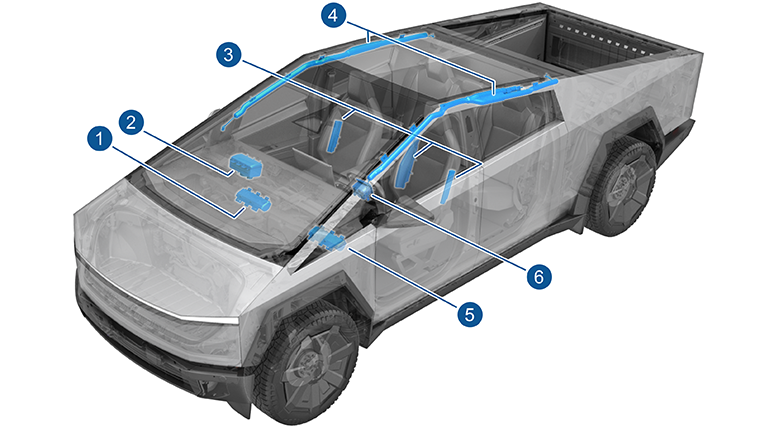
Cybertruck has a variety of airbags which, when combined with seat belts, are intended to safely dissipate the occupant’s kinetic energy during an impact. The amount of kinetic energy airbags must absorb depends on the change in velocity of the vehicle and the mass of the occupant.
Advanced multi-stage airbags, like those in the front row of Cybertruck, are able to adjust the energy absorption for different speeds or passenger sizes. Seat sensors, such as the Occupant Classification System (OCS), and seat track position give an indication of the passenger's size and distance to the dashboard while the crash accelerometer and velocity measurements allow for an understanding of the occupant speed. The information is continually fed into the Restraint Control Module (RCM) where, in the event of a crash, it can determine the appropriate energy absorption needed from the seat belts and airbags.
 |
|---|
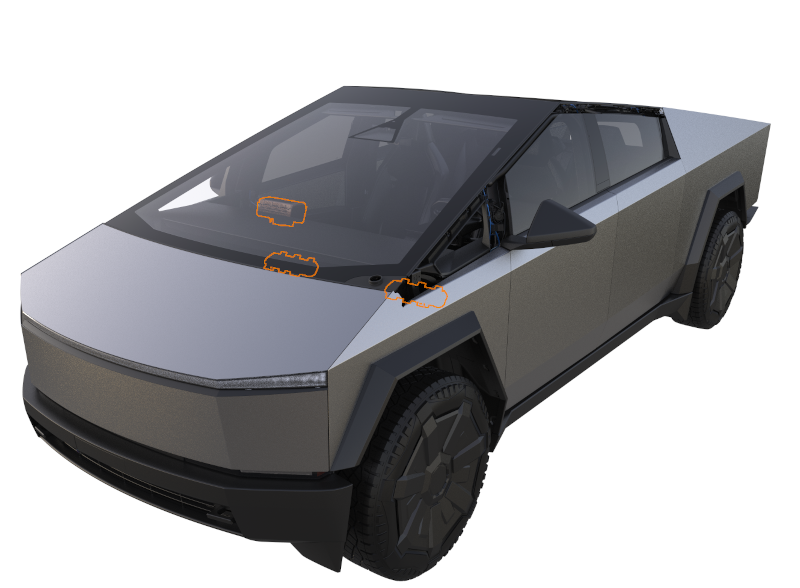
| 1. Front passenger airbag 2. Curtain airbag – RH 3. Lap belt pretensioner – RH 4. Seat belt retractor – 1st row – RH 5. Passenger seat mounted airbag 6. Seat belt retractor – 2nd row 7. Seat belt buckles – 2nd row 8. Rear Center Pretensioner 9. Driver seat mounted airbag 10. Driver seat mounted far side airbag (inboard) 11. Seat belt retractor– 1st row – LH 11. Lap belt pretensioner – LH 12. Seat belt buckles – 1st row 13. Curtain airbag - LH 14. Driver airbag – LH 15. Knee airbag – LH 16. Knee airbag – RH |
| Location of Airbag and Seat Belt Components |
 |
|---|
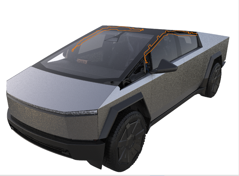
| 1. Accelerometer Front Left (Front Left Satellite Impact Sensor) 2. Accelerometer Bumper Mid-Left (Front Middle Left Satellite Impact Sensor) 3. Accelerometer Bumper Mid-Right (Front Middle Right Satellite Impact Sensor) 4. Accelerometer Front Right (Front Right Satellite Impact Sensor) 5. Accelerometer B-pillar Left 6. Accelerometer B-Pillar Right 7. Pressure Sensor FL Door 8. Pressure Sensor FR Door 9. Pressure Sensor RL Door 10. Pressure Sensor RR Door 11. Restraint Control Module (RCM) |
| Location of Accelerometers and Pressure Sensors |
Seat belts in the front row are equipped with a variable load limiter, which adjusts the amount of energy that the seat belts absorb from the occupant. The load limiter is integrated into the seat belt retractor assembly. To minimize the risk of occupant injury, the variable load limiter can be deployed to adjust to a softer load limiter to lessen the maximum tension in the seat belts. When variable load limiters are deployed, the energy absorbed by the seat belts is decreased, which allows the seatbelt and airbags to balance the occupant energy more effectively and result in less injury. The variable load limiter system is only deployed in frontal /angular impacts where the airbags are most effective. In cases with only lateral motion or any rear impact, the seat belts absorb as much energy as possible.
Seat belt pretensioners are used to remove slack from the seat belt, which helps to absorb occupant energy. Retractor pretensioners pull on the shoulder belt, while lap (or anchor) pretensioners pull on the lap belt. Front row seats have both shoulder and lap pretensioners. The shoulder belt pretensioner is located in the lower B-pillar, and the lap pretensioners are mounted to the seat frame. Second row seats have a retractor pretensioners on all three seating positions (LH/RH/Center).
The 1st row and 2nd row outboard occupants are protected in crashes with lateral motion (side, angled, or offset type crashes) by side curtain airbags. The curtain airbags deploy down from the upper trim area. Seat airbags inflate from the outboard seat bolsters to soften occupant hip and torso contact with the door trim in the 1st row. Cybertruck is equipped with knee airbags, which deploy in frontal crashes. However, the knee airbag will not deploy when a belted occupant is seated in the passenger seat, and the seat is forward of a pre-determined point in the seat track travel (closer to the airbag module). The RCM dictates stage 2 threshold based on signal severity. The Seat Track Position Sensor (STPS) will determine the knee airbag deployment strategy for belted occupants.
In the event of a collision with the drive rail on, the primary and secondary pyrotechnic fuse is deployed to isolate high voltage from the high-voltage (HV) battery. All crash modes, including front, side, rear, or roll, that exceed the programmed threshold will trigger the pyrofuse. The fuse disables high voltage by breaking continuity.
All deployable safety systems, such as airbags and seat belt pretensioners, are single-use pyrotechnic devices and must be replaced after deployment. All partially deployed devices (except load limiters) will completely dispose of their pyrotechnic component within a short period of time of pretensioner deployment. Seat airbag deployment will require a full seat replacement in the event of deployment. While deployed safety devices are designed to be inert after a crash to protect occupants and first responders, any pyrotechnic device should be handled with all proper procedures and care according to the vehicle Service Manual.
Warning
Although the airbags and pretensioners are designed to be triggered electrically, they are pyrotechnic devices and could deploy unexpectedly—even when not connected to an electrical source—if proper transport, storage, and handling methods are not followed. Always follow Service Manual procedures when diagnosing or repairing the TSRS.
Warning
Accidental deployment can cause damage and personal injury. Always refer to the Owner's Manual for correct use of the Tesla Supplemental Restraint System (TSRS) and seat belt systems, and refer to the Service Manual for correct fitment, repair, and disposal of system components.
Component Specificationslink
Restraint Control Module (RCM)link
The TSRS is controlled by the RCM, which includes fault detection and warning circuits. If a fault is detected, an indicator light in the instrument panel notifies the driver. Alerts (with the Electronic Control Unit (ECU) prefix "RCM2") are also retrievable using vehicle controller area network (CAN) logs, vitals, or Periscope.
The RCM is calibrated specifically for the vehicle model. It contains accelerometers and gyroscopes to measure forces acting on the vehicle and circuits for monitoring the condition of all pyrotechnic devices. It is the primary device that commands the deployment of all TSRS components. During a deployment, the system runs a current through individual components to trigger the pyrotechnics. Each stage and part has its own independent wire loop for this triggering signal.
The RCM monitors the TSRS's electrical components and circuitry when the drive rail is on. The RCM uses an internal six-axis inertial measurement unit (IMU) to monitor all 3 angular velocities, as well as three-dimensional (3D) accelerations of the vehicle. The module is located under the center display.
The acceleration data from the RCM is broadcast on Left CAN and RCMPRIVATE CAN (connection between RCM, EGGRIGHT, GTW and ICR) to other vehicle systems for use in the traction control, stability control, and other dynamic control algorithms. If the internal sensor detects a high acceleration event, it looks to data from the satellite sensors to determine the type and severity of the crash.
Cybertruck is equipped with an event data recorder (EDR). The EDR records data related to vehicle dynamics and safety systems when the system senses a crash or a crash-like situation, such as hitting a road obstacle. This data is stored in the vehicle's Restraints Control Module (RCM). The module is able to store data for a maximum of three independent events, where non-deployment events can be overwritten by subsequent events, deployment events cannot. If both data records have been stored as full deployments, the module will not allow any additional events to be stored. The RCM needs to be replaced after any deployment event since the data cannot be overwritten. Data can be accessed from a Tesla EDR by visiting https://edr.tesla.com/help. The EDR system is entirely separate from the data storage on the gateway after a crash is detected.
When deployment occurs, the RCM sends a collision detection CAN message to vehicle controllers which:
- Switches on the hazard lights.
- Unlocks all doors.
- Unlocks the trunk.
- Opens the glove box for access to registration papers.
- Vents windows.
The gateway will:
- Upload a snapshot of CAN logs around the event.
- Package the RCM information.
- Attempt to gather any Automated Emergency Braking or Side Collision Avoidance data from the driver assistance system (DAS).
The vehicle will also attempt to package these items and immediately upload them to vehicle CAN logs. If this process fails, there is currently no retry mechanism, and the data will have to be pulled manually from Toolbox.
The RCM performs diagnostic monitoring of TSRS electrical components and deployment loops for malfunctions while the drive rail is on. The module requests the instrument cluster to display the airbag warning indicator light if a malfunction (bad deployment circuit or missing sensor) is detected. The RCM stores a Diagnostic Trouble Code (DTC) and sends a CAN message that is stored in the vehicle log.
Sensor Detailslink
Cybertruck uses a combination of accelerometer sensors (impact sensors) and pressure sensors to sense the impact.
| Sensor | Quantity |
|---|---|
| Accelerometer Front Left (Front Left Satellite Impact Sensor) | 1 |
| Accelerometer Bumper Mid-Left (Front Middle Left Satellite Impact Sensor) | 1 |
| Accelerometer Bumper Mid-Right (Front Middle Right Satellite Impact Sensor) | 1 |
| Accelerometer Front Right (Front Right Satellite Impact Sensor) | 1 |
| Accelerometer B-pillar Left | 1 |
| Accelerometer B-Pillar Right | 1 |
| Pressure Sensor FL Door | 1 |
| Pressure Sensor FR Door | 1 |
| Pressure Sensor RL Door | 1 |
| Pressure Sensor RR Door | 1 |
The RCM uses the data from these sensors to determine if a collision is severe enough to warrant any airbag and / or seat belt pretensioner deployment. Data from the front left hand (LH) and right hand (RH) accelerometers are compared to determine if the impact contains offset or is angular.
Both the accelerometers and the pressure sensors communicate with the RCM with a Peripheral Sensor Interface (PSI-5) communication protocol. This protocol is used in automotive electronics to connect peripheral sensors to the electronic communication unit. This allows multiple sensors to be connected to the same line (a bit like multiple CAN nodes that communicate on a single CAN network), and it allows the RCM to detect hardware failures such as open loop, short, and it can detect if a wrong sensor is installed.
Accelerometerslink
Cybertruck is equipped with six accelerometers. Accelerometers, also called impact sensors, contain a device that monitors the attached component's relative acceleration to the RCM.
Two outer front accelerometers detect front and rear impacts. They are oriented on an oblique angle toward the Y direction .
Two Front End Module (FEM) bracket accelerometers (bumper accelerometers) detect front and rear impacts.
Two B-Pillar Accelerometers detect side impacts. They are oriented in the lateral direction.
Pressure sensorslink
Cybertruck is equipped with four pressure sensors. Pressure sensors are Piezoelectric pressure sensors mounted inside the front and rear doors and measure the dynamic pressure change caused by deformation of the door caused by side impact. They require a sealed door compartment to work properly. The inputs from the pressure sensors are processed by the RCM to deploy the side airbags and the seat belt pretensioners.
Warning
Always reinstall or replace any plug or tape removed from a door shell when servicing any component inside of the door. The pressure sensors are calibrated to respond to pressure changes within the door in the event of a side impact. Opening more holes in the door creates additional escape paths for air, which diminishes the sensor's ability to accurately detect a side impact, and can negatively affect airbag deployment.
Two pressure sensors in the front doors and two pressure sensors in the rear doors.
Seat Belt Buckle Switchlink
All five seat belt buckle switches are fitted to determine the deployment strategy for lap and shoulder pretensioners and variable load limiters. The front row seats each contain a shoulder pretensioner, lap pretensioner, and a variable load limiter, while the 2nd row seats only contain shoulder pretensioners with a non-variable load limiter. For the front passenger seat, the seat belt buckle switch also determines the active vent deployment strategy for larger occupants.
Occupancy Sensorslink
The individual occupancy sensors communicate to different vehicle controls (as explained in the below sections), but all occupancy statuses (except front right) report back to VCLEFT. This allows the other vehicle controllers, specifically the RCM to consume the occupancy signals from one source. When diagnosing the vehicle, it is important to check the occupancy sensor at the vehicle controller which it reports to, as well as that controller's communication back to VCLEFT.
Cabin Radarlink
 |
|---|
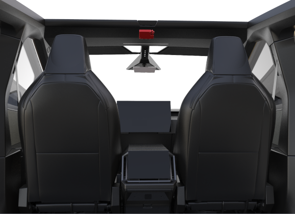
| Cabin Radar (Driver seat occupancy detection) |
Cabin Radar (ICR), located behind the front header, detects occupancy in only the driver's seat. The ICR communicates on RCMPrivate CAN. The ICR emits a radio frequency wave, which bounces off the surroundings and returns to the module. The ICR algorithm then converts the reflected signal's distance and velocity into object or human detection. This detection is based on the object's movement, size, and location.
Serviceabilitylink
Note
Avoid placing objects directly in front of the ICR, as this may obstruct occupant detection.
Tip
The Cabin Radar can be identified with the cfg_InteriorCabinRadarType vehicle configuration. Cabin Radar will have the TESLA configuration.
When diagnosing issues of the system, use the following terminology:
- False Positive - There is no occupant in the seat, but the system is detecting an occupant.
- False Negative - The seat is occupied, but the system is not detecting an occupant.
A false positive can lead to the vehicle staying powered on with no occupants in the cabin resulting in loss of range, as well as walk away lock not operating at expected. A false negative can lead to the vehicle not turning on when someone is in the cabin.
When investigating complaints about ICR, be sure to check for the state of the door, buckle, and brake pedal pressed.
Occupant Classification Systemlink
Occupant Classification System is a system that detects who is sitting in the front passenger seat. OCS is made up of two individual components: the OCS Electronic Control Unit (ECU) and the OCS bladder. The bladder is a urethane skin filled with silicone. It converts the A-surface load to a mechanical fluid pressure signal. The OCS ECU, also known as the Smart Digital Pressure Sensor (SDPS), senses fluid pressure changes and applies calibration tables and algorithms to make the classification decision.
There are pushpins to ensure the bladder is located correctly between the foam and the seat cushion pan and the SDPS mounts underneath to the seat cushion pan. The OCS communicates via local interconnect network (LIN) to the right vehicle controller (VCRIGHT).
VCRIGHT then communicates the status to the RCM (RCM2) using a CAN signal. The RCM uses this information to determine whether to enable or suppress the deployment of the front passenger airbag and, if applicable, the corresponding knee airbag. The OCS ECU sends a classification to the RCM where the passenger airbag light state is determined by the RCM's receipt of the OCS classification. The RCM transmits a signal to set on the UI indicating the passenger airbag state light (PASS AIRBAG OFF/ON).
Calibration of the system when it is new is done using an ODIN routine.
Note
Seat position, occupant size, and weight distribution affect the sensed values. An occupant whose weight is near the classification thresholds can cause the airbag deployment strategy to toggle between regions.
| Front Passenger Seat Occupancy | Passenger Airbag Indicator Touchscreen | Passenger Airbag Stages |
|---|---|---|
| Seat empty, child seat, or small child | PASS AIRBAG OFF | None |
| Occupied (>100 lbs) | PASS AIRBAG ON | 1st and 2nd |
The RCM notifies the occupants of the disable status by displaying the PASSENGER AIRBAG ON / OFF indicator in the MCU. If a fault is detected, the OCS sends a message to the RCM. The RCM responds by sending a command message to the touchscreen to display the TSRS airbag indicator.
Resistive Padslink
 |
|---|
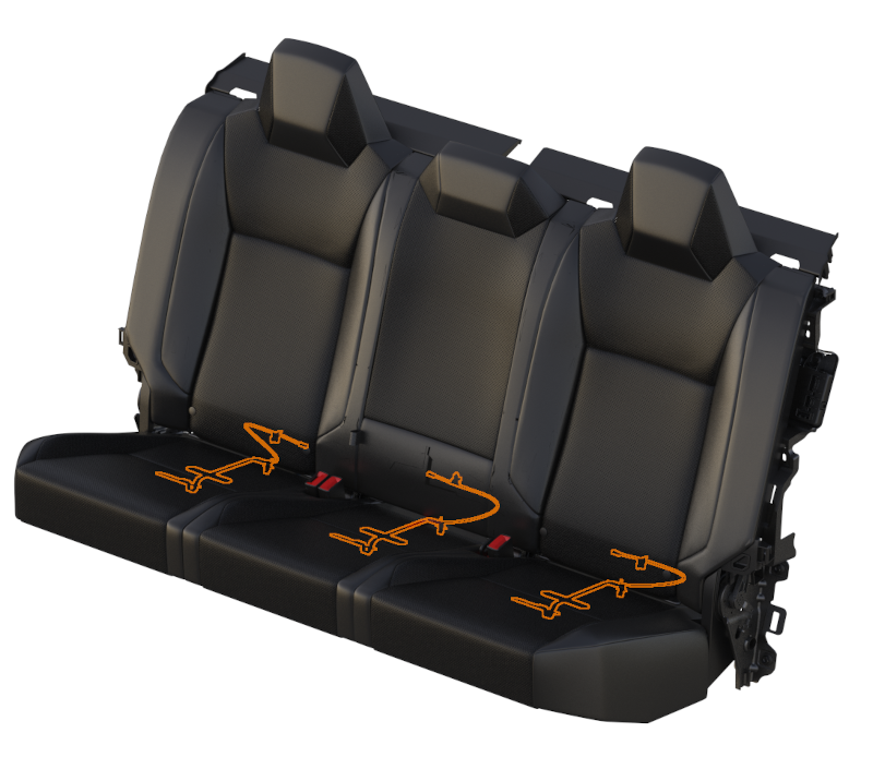
| Rear seat resistive pads |
When occupied, the resistance should read 1 kOhm. When unoccupied, the resistance should read 11 kOhm. Each rear seat has its own input on VCREAR, which communicates that signal to VCLEFT.
The resistive pad (sometimes referred to as the occupancy sensor or seat belt reminder) is a circuit of switches and resistors distributed throughout the cushion connected in both parallel and series. Having the sensors distributed throughout the cushion helps to prevent situations where small items might trigger the seat belt reminder indicator. The resistive pad in conjunction with the seat belt buckle switch, indicate whether an occupant is seated in the seat with the seat belt buckled. This symbol is placed on the center display and is visible at all times. In addition, each individual seat can show a seat belt telltales in the overhead view of all seats. Depending on the vehicle region, there are various audible and visual chimes indicating to the customer that an occupied seat does not have the seat belt buckled. The performance and behavior of these audible and visual chimes differ region to region. The UI will display any visual indication of an unbuckled seat.
When occupied, the resistance should read 1 kOhm. When unoccupied, the resistance should read 11 kOhm.
Passenger Seat Track Position Sensorlink
The Seat Track Position Sensor (STPS) is used to determine the distance between the passenger seat and the front airbag. Information from the STPS is used by the RCM to modify active vent and seat belt load limiter deployment times, as well as suppress the knee airbag (when seat belt is buckled) if the seat is forward of a pre-determined point in the seat track travel (closer to the airbag module). The STPS is a Hall-effect sensor mounted on the outboard seat track of the passenger seat. The seat track includes a metal bracket that shunts the STPS magnetic circuit, creating two states of seat position. The shunted state represents a rearward seat position. The non-shunted state represents a forward position where metal is not present next to the sensor. These two states are inputs to the RCM.
The STPS is connected to VCRIGHT. VCRIGHT then forwards the information to the RCM.
The sensor is attached to the seat track with one screw.
On some vehicles, the STPS is also located on the driver seat. The STPS on driver seat is unused in vehicle.
Deployable Restraintslink
Driver Airbaglink
The driver's airbag deploys from the steering wheel. It is a two stage circular airbag with active vent. The first stage is for less severe frontal impacts. The second stage shall only deploy in more severe cases to get the bag into position faster and provide increased stiffness. The active vent helps to lower the stiffness of the bag later in the event, the vent is used in cases where perpendicular contact with the bag is made (no offset or angle in the impact).
Knee Airbaglink
 |
|---|
| Driver knee airbag |
The single-stage passenger knee airbag is located inside the lower part of the instrument panel. Occupant kinematics are improved by the knee airbag in situations where the occupant is unbelted. In all frontal cases, when a belted occupant is seated in the passenger seat, and the seat is forward of a pre-determined point in seat track travel (closer to the airbag module), the passenger knee airbag will not deploy. When the belted occupant is seated in the passenger seat and the seat is behind the pre-determined point in seat travel (further away from the airbag module), the knee airbag will deploy. There is a potential the knee airbag may deploy independent of the passenger frontal airbag in some cases where the seat belt is not buckled, but an occupant is detected by the OCS.
Passenger Airbaglink
The passenger airbag deploys from the top of the instrument panel, it is a two stage airbag with an active vent. The airbag contains `bull horns' to help control the lateral and rotational motion of the head, particularly in frontal impacts with a lateral component. The second stage will deploy in more severe cases to get the bag into position faster and provide increased stiffness. The active vent helps to lower the stiffness of the bag later in the event, the passenger active vent is used for forward seating positions or with a long delay for large unbelted occupants when no angle or offset is detected. Airbags not fitted with active vent have larger discrete vents.
Curtain Airbaglink
 |
|---|
| Curtain airbag |
The side curtain airbags are located under the headliner trim on the LH and RH sides of the vehicle. They inflate over the full area of the front and rear side windows to form a cushion, protecting the occupant’s head from contact with the window frame or pillar(s) in a side-impact collision. The side curtain airbag deploys downwards from the top and drapes over the entire glass area. The side curtain airbags stay inflated for a few seconds after a collision in case the vehicle rolls over. In some side impacts, only one side will deploy, the struck side.
Seat Outboard Side Airbaglink
A single chamber side airbag located on the outboard portion of the front row seat. The seat side airbags are deployed from the outboard side of the seat, forming a cushion between the occupant and the door, protecting the occupant’s torso and pelvis area during a side impact. These airbags only deploy on the struck side of side impacts.
Side seat airbags are built into the seat themselves. They are not serviceable. If deployed or damaged, the seats will need to be replaced.
Seat Inboard Side Airbag (far side)link
 |
|---|
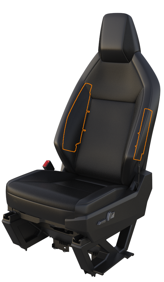
| Seat airbag locations |
A single stage airbag located on the inboard portion on the front driver seat. The far side airbag forms a cushion between the driver and passenger seat during a side impact.
Pretensionerslink
The driver and 1st row passenger seat belt pretensioners are a dual pretensioner system. The lap belt pretensioners are mounted on the seat, and the shoulder belt pretensioners are integral with the retractors. The 2nd row seats each have a single shoulder pretensioner. The lap belt pretensioners will deploy 5ms after the retractor pretensioners to optimize for removal of slack in the belt.
Any time an airbag deployment occurs, and the occupant is belted, the seat belt pretensioners are also deployed. These devices are designed to work together to safely absorb occupant energy. The pretensioners will not be deployed if the corresponding seat belt buckle is unlatched. If the signal is not available or is faulted at the time of deployment, the RCM will assume the seat belts are buckled, and the pretensioners will be deployed. It is possible that pretensioners can be deployed independently of the airbags.
The RCM directs current through the deployment loops to the initiator to deploy pretensioners. Current passing through the initiator ignites the material in the canister, producing a rapid generation of gas. The gas produced from this reaction deploys the seat belt pretensioners, which remove slack in the lap and / or shoulder belts. The process is one-time only and cannot be reversed. The component needs to be replaced after every deployment.
Load Limiterslink
Seat belts in the front row are equipped with a deployable load limiter, which lowers the peak force that the seat belts absorb from the occupant. To minimize the risk of occupant injury, the load limiter selector can be deployed to decrease the maximum tension of the seat belts. When the load limiter selector is deployed, the peak force absorbed by the seat belts decreases, which allows the airbags to absorb more occupant energy. The system is only deployed in medium and high severity frontal impacts where the stage 2 airbags are deployed. In cases with only lateral motion or any rear impact, the seat belts absorb as much energy as possible. The load limiter is contained within the retractor housing.
Pyrofuse Disconnectlink
There is a primary and secondary pyro-disconnect installed inside the Ancillary Bay of Cybertruck and joins one half of the High Voltage Battery to the other. Specific high voltage battery events, such as over-current, overcharge, over-discharge, in addition to airbag deployment will result in the deployment of the pyrofuse disconnect. Refer to the High Voltage Battery section for additional information.
Steering Columnlink
The steering column is designed to absorb energy and collapse during frontal collisions to decrease the chance of injury to the driver. The column has collapsible travel. A deformable wire adds resistance to the collapsing motion. If the vehicle has been in a collision that caused driver airbag deployment, the column should be inspected to check whether it collapsed.
Warning
The steering column must be inspected whenever the driver airbag has deployed. Refer to Collision Repair Procedure SRS Inspection and Component Replacement.
Pedestrian Warning Systemlink
 |
|---|
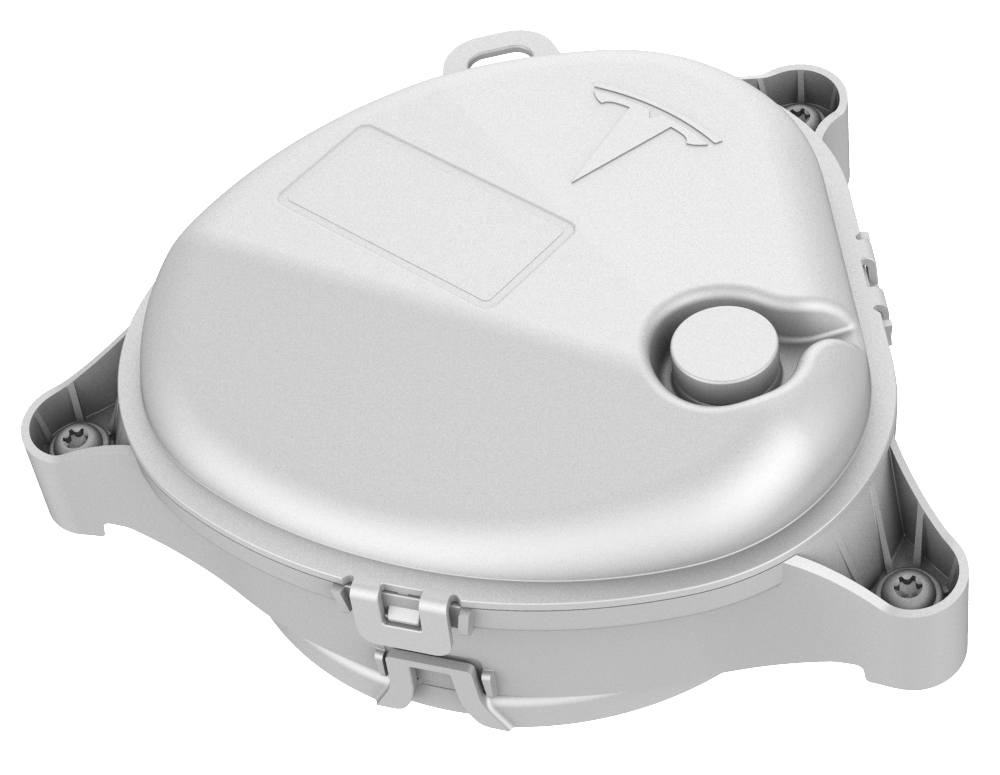
| Pedestrian warning speaker component |
The Pedestrian Warning System (PWS) encompasses a speaker enclosed in a box at the RH front of the vehicle, located on the front fascia. The PWS is a legal requirement based on region. The specifics of the requirement (pitch of noise, speed of vehicle, etc.) are dependent in which region the vehicle is located. Electric vehicles traveling at slow speeds must emit a noise to warn pedestrians of motion. As soon as a vehicle is put into gear, the speaker emits a noise.
Drivelink
The speaker emits a noise while the vehicle is in drive. As the vehicle accelerates, the noise goes up in pitch. Once the vehicle reaches a speed of 30kph/19mph, the noise begins to fade out. The forward motion noise sounds similar to a spinning fan. Tesla has taken precaution to minimize the noise for customers inside the vehicle. The intent is that the pedestrian warning speaker is only heard from outside the vehicle.
Reverselink
When the vehicle is in reverse, the noise emitted by the PWS needs to be heard at the rear of the vehicle. The sound while in reverse is more of a tone and is emitted by the rear right PWS. The noise in reverse intentionally sounds different than the noise in drive. No matter what the speed, the pedestrian warning speaker will emit a noise while in reverse.
Communicationlink
The PWS receives messages via the touchscreen. The drive inverter reports the gear and the speed of the vehicle to the gateway. The gateway then communicates this information to the touchscreen, where the audio system then transmits the appropriate noise based on these inputs. The audio system in the vehicle includes a microphone, the amplifier that then communicates to all speakers. If there are issues with the PWS, a good first debug step would be to check the other speakers in the vehicle to pinpoint if the issue is with the audio system as a whole or the pedestrian warning speaker.
Serviceabilitylink
Gateway Configurationslink
| Config | Value | Key | Description |
|---|---|---|---|
| restraintsHardwareType | 52 | NA_CT | NA for Cybertruck |
ODIN routineslink
| Routine | Description |
|---|---|
| PROC_RCM_X_SERVICE-TASKS | This routine runs through all the individual self tests on each of the safety components, as well as any calibration / configuration routines necessary for the RCM. |
Other useful vitalslink
PCBAID: This gives the ID of the PCBA within the RCM. For Cybertruck, this ID is 6.
AssemblyID: This gives the ID of the Assembly, or enclosure of the RCM. For Cybertruck, this ID is 2. Cybertruck RCM is unique as it has sealed connectors.