Windowslink
Last updated: October 20, 2023
General informationlink
This section of theory of operations gives an in depth view of the operation of the windows. It is split up into four main sections:
- Component Description: This section details what the component is and where it is located on the vehicle.
- System Architecture: This section describes how the components interact with each other.
- User Interaction: This section describes how the user interacts with the system. Details are given on all the different configurations in which the component can be used.
- Component Operation: This section details how the component achieves its intended function, including details on the signals that get sent between components.
Component Description:link
Switchpacklink
 |
|---|
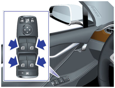
| The Driver's Side Window Switchpack |
The window switches are plastic push-pull levers mounted on the driver's side arm rest. These switches allow control of all four power windows in the vehicle.
All other doors also have a single window switch used for control of that window only.
The switches have 5 positions:
- Neutral: This is the undisturbed switch state. No effect on the window position.
- Down Partial: Pressing the switch down lightly will lower the window as long as the switch remains in this position. Use this setting to lower the window a custom amount.
- Down Full: Pressing the switch down all the way will fully lower the window. The motor is driven regardless of switch position. Its state is latched until an overcurrent condition causes the motor state to unlatch.
- Up Partial: Same as down partial, except the window moves up.
- Up Full: Same as down full, except window moves up.
Below the lever switches on the switch pack, there is a rear window lock button which prevents the rear passengers from raising or lowering their respective power windows.
Door Control Moduleslink
 |
|---|
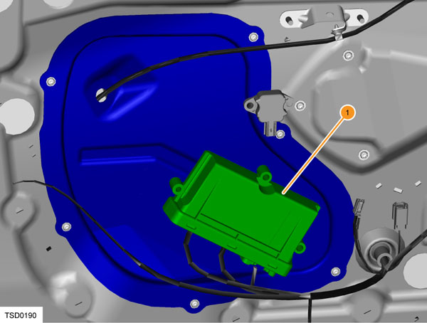
| 1. Door control module |
A door control module is located in each front door. Each door control module controls the front and rear door for its respective side. The door control modules are designed by a third party company called Pektron. The door control modules have other purposes apart from windows.
For the purpose of window operation, the door control modules act as a CAN/LIN gateway between the window switchpacks and the window regulators. The driver/passenger door modules are connected on the body CAN bus (see System Architecture).
The driver door module (DDM) and the passenger door module (PDM) are identical. These modules self-identify their position on the vehicle through a combination of an output from the gateway (GTW), and unique vehicle harness wiring. The "GTW_rhd" output determines whether the vehicle is LHD (0) or RHD (1). The passenger door wire harness grounds an input circuit of the module, which identifies it as the passenger door module. From these two inputs, each door module determines if it is on the left hand or right hand side of the vehicle, and whether it is the driver door module or passenger door module.
When a module is replaced, it needs to be formatted to the vehicle by selecting the appropriate door controller and running the "Pektron Body Controls Configuration" in Toolbox. This stores the module configuration in non-volatile memory. The vehicle firmware also needs to be updated upon replacing the door module.
Window Regulatorlink
 |
|---|
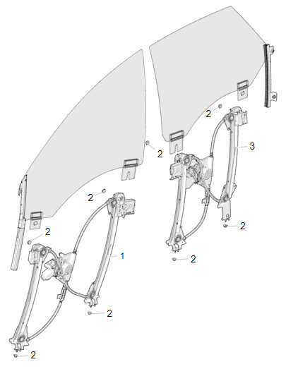
| 1. Window Regulator Assembly - Front Door 2. M6 Hex Nut 3. Window Regulator Assembly - Rear Door |
The window regulators are designed and manufactured by a third party called Inteva.
The window regulators contain a DC motor with a right angle worm drive gear box, a DC motor controller, and a cable/pulley system which translates the rotation from the motor into linear motion of the windows.
The cables pull metal guides up the two rails on the regulator. These metal guides bolt directly to the window glass, and hold the glass in place. The position of the glass can be adjusted by loosening the clips in the metal guides. This operation can be used to correct glass flush issues.
The regulators on Model S are 'smart regulators', meaning that they contain an encoder which allows them to accurately know the position of the window at all times. This ability is dependent on window calibration (see component operation).
Warning
Model S window regulators do have overcurrent monitoring and will therefore stop if an obstacle is detected. Because Model S window regulators are not classified for pinch detection, features like 'global closing' are unavailable. Avoid getting fingers and other body parts in the path of a closing window to prevent injury. Obstacles in the closing path can also affect calibration.
Warning
The window regulator is a non-serviceable component. If there is an issue with the window regulator operation, replace the component.
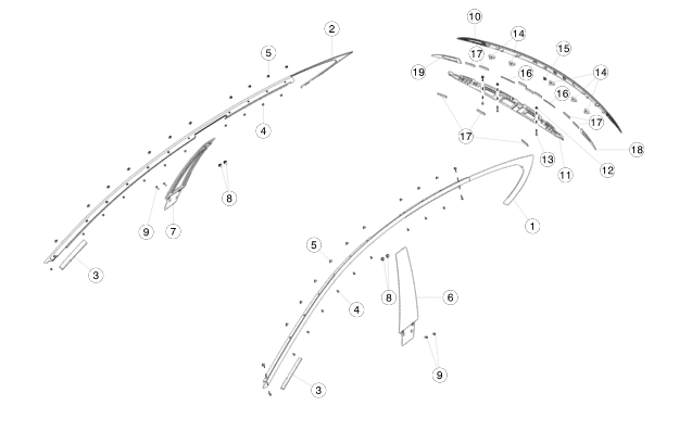
Front/Rear Fixed Quarter Glass:link
 |
|---|
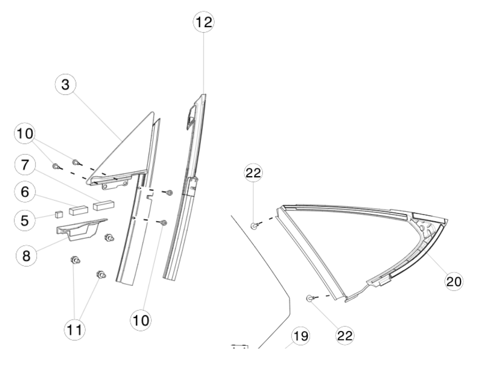
| 3. Front Fixed Quarter Glass 12. Front Fixed Quarter Glass Seal 20. Rear Fixed Quarter Glass |
The front fixed quarter glass sits between the A pillar and the front door window. The seal attached to the front fixed quarter glass is vital for preventing water ingress through the side of the door window. The door window presses against the rubber seal upon door closure. The quality of the seal is dependent on window alignment.
The rear fixed quarter glass sits between the C pillar and the rear door window. The seal prevents water ingress at the rear window edge.
Bright Work/B Pillar Applique:link
 |
|---|
| 1. Bright molding 6. B Pillar applique |
The bright work is a trim installed around the top perimeter of the front and rear windows. The bright work hangs over the glass of the window and contains a seal which the window presses into to prevent water ingress. The quality of the seal is dependent on the relative alignment between the window and the bright work seal. Sealing is provided along the inside edges of the windows by rubber on the B pillar applique.
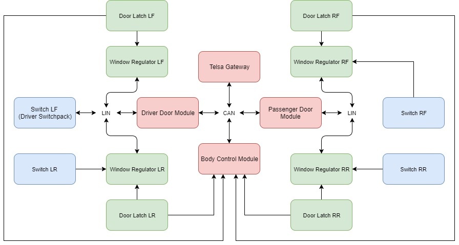
System Architecture:link
The following diagram represents the communication architecture of the window system on the Model S.
 |
|---|
| Windows system architecture |
Each window regulator is connected to LIN, to its corresponding window switch and to its corresponding door latch.
Note
This diagram is for LHD Model S only.
Note
LHD Model S has the driver switchpack on the left hand side of the vehicle. RHD has the driver switchpack on the right hand side of the vehicle.
Note
The driver switchpack is always connected directly to the LIN bus of the vehicle and is not hard-wired directly to the window regulator as are all the other switches.
Note
RHD Model S architecture diagram would have Switch RF connected to the LIN bus and not the window regulator, and switch LF connected to the window regulator and not the LIN bus.
Theory of Operationlink
The process of controlling a window involves several modules/communication protocols in going from user input to window motion. This section describes the flow of information behind controlling a window. Furthermore, special cases in window operation are described, such as short drop.
Operating a Window from the Local Switch:link
This section describes the process of operating a window from a local switch, meaning the switch corresponding to the window adjacent and not on the driver switchpack. This is the only case for the three passenger power windows.
- The switch lever is pressed/pulled by the user.
- Each switch position causes a certain voltage level that is read by the window regulator (see component operation). The window regulator reads this voltage level and therefore knows the position of the switch.
- If the switch position is down/up partial, the regulator will drive the motor until the window reaches the top/bottom of travel, or the switch position changes to any other state.
- If the switch position is down/up full, the regulator will drive the motor until the window reaches the top/bottom of travel, or the switch position changes to the opposite down/up full state.
Operating a Window from the Driver Switchpack:link
The driver switchpack is special because it is not connected directly to any window regulator. Instead, it connects to the Driver Door Module via LIN bus.
- The switch lever is pressed/pulled by the user.
- Each switch position causes a certain voltage level that is read by the switchpack.
- The switchpack transmits a LIN signal to the driver door module.
- The driver door module makes a decision depending on the active switch:
- If the switch pressed/pulled corresponds to a window on the driver side of the vehicle, then a LIN signal is sent to that regulator and the regulator acts accordingly.
- If the switch pressed/pulled corresponds to a window on the passenger side of the vehicle, then:
- The driver door module sends a CAN signal over the Body CAN bus to the passenger door module.
- The passenger door module processes the CAN request and sends an appropriate LIN signal to the window regulator.
- The regulator acts accordingly.
Window Short Drop Functionality:link
Because the bright molding on the Model S overhangs the windows, the windows must be lowered in order for the door to be opened without interference. This is referred to as a 'short drop'.
- The window travels to or near the topmost position. If the window is in a position where the glass will hit the bright molding upon opening the door, the regulator will send a notification via LIN to the door control module to enable short drop for that window.
- Once short drop is enabled, the door control module will wait for a door open request signal from the interior or exterior door handles.
- Once the signal is received, the door control module sends a command via LIN to the window regulator to perform a short drop.
- The window regulator controller will lower the motor until it reaches a pre-calculated position where the glass will clear the bright molding.
- The door control module waits 100 ms after requesting window short drop to activate the door latch, releasing the door.
Locking the Rear Windows:link
On the driver switchpack there is a button which prevents the rear windows from operating. This button is recommended to be active when children are present in the rear seat.
- The driver presses the 'lock rear windows' button, which sends a signal via LIN to the Pektron driver door module.
- The driver door module communicates via CAN to the passenger door module that the switch is enabled, which sends it to all the regulators.
- All rear window regulators ignore all voltage inputs from the local window switches, thus preventing window motion from the current state.
Window Functionality Upon Leaving Vehicle:link
If the vehicle is turned off when the window is left open, the window will remain in the current state, and will not close automatically, as is the case with some other vehicles. This is because the pinch detection on Model S is not classified to prevent limb injury, even if the window does reverse upon stalling.
Speed Control of the Window:link
Unlike other parts of the vehicle, the windows are not speed controlled. When the window moves up and down, the regulator will drive the motor at a constant voltage with no feedback. The control system is open loop, meaning that it will not actively compensate for loads on the window to maintain a set speed.
Pinch Detection:link
The windows on Model S also contain pinch detection. If the window detects a stall somewhere not at the endpoint of the travel, then pinch detection will activate and the window motor will reverse travel for up to half of the window opening.
Diagnosticslink
Window switch detailslink
As stated before each window switch has 5 positions:
- Up Full
- Up Partial
- Neutral
- Down Partial
- Down Full
The purpose of this section is to give additional insight into how the regulator detects which of these 5 states the switch is in (for switches with a direct connection to to the regulator). The driver switchpack uses the same voltage logic when it internally reads the position of each switch and sends the position via LIN to the driver door module.
Each local window switch (not driver switchpack) is connected to other components via a single 4 pin connector. These 4 pin connectors are:
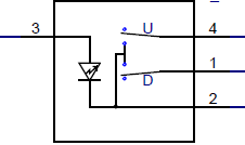 |
|---|
| Window switch as shown in the wiring diagram |
| Pin | Type | Termination |
|---|---|---|
| 1 | Logic Output | Down |
| 2 | GND | Door Module |
| 3 | 12V | Door Module |
| 4 | Logic Output | Up |
The internals of the switch can be represented like this. Both arrows represent a physical lever inside the switch.
 |
|---|
| Internals of window switch |
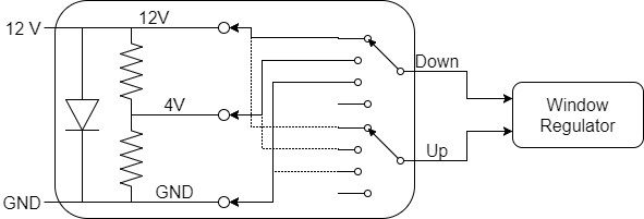
The Door module supplies the window switch with 12V and ground (GND) to illuminate the switch. Internal to all the local switches is a voltage divider which creates three voltage levels, 12V, 4V, and GND. The switch lever position corresponds to moving the 'Down' or 'Up' selector in the schematic to the appropriate position. To demonstrate, the following Picoscope traces were taken of pin 1 on the rear left passenger window switch on the Model S.
Example 1: If the switch is in its Neutral position, both levers are as in the picture, so connecting both the Up and Down pin to 12V. 0V will be measured between pin 1 and pin 4.
Example 2: When the switch is in the Partial Down position, pin 1 (Down) is connected to 4V, pin 4 (Up) is connected to 12V. 8V will be measured between pin 1 and pin 4.
Expected voltage levelslink
The expected voltages on each of the signal pins compared to ground of the switch.
| Switch State | 'Up Voltage Signal' | 'Down Voltage Signal' |
|---|---|---|
| Neutral | 12V | 12V |
| Up Partial | 4V | 12V |
| Up full | 0V | 12V |
| Down partial | 12V | 4V |
| Down full | 12V | 0V |
By reading this combination of voltages as inputs, the window regulator is commanded to control window motion appropriately.
The switches operate identically in the driver switchpack, except the reading of switch position (voltage table above) is done internally in the switchpack. A microcontroller reads the switch position, and transmits this switch position as a LIN signal to the window regulator.
Calibrationlink
The window regulator contains an incremental encoder that tracks position changes. However, it does not report or keep track of the absolute position. Therefore the regulator must learn the endpoints of the window. This is done through window calibration.
Calibration of the window is achieved by cycling the window from bottom to top. Upon reaching the bottom of window travel, the regulator will detect the stall current in the motor, and see the encoder failing to move further. It zeroes this position in memory after seeing the stall current for 2 seconds, and then as the window is moved to the topmost position, the regulator determines the encoder distance to the next stall position. Once the top stall condition is achieved for 5 seconds, the regulator will always keep track of the encoder position relative to the two endpoints. This is how it always knows where the window is.
When the window is moved by a switch to where it hits an endpoint, it will monitor the current to detect when stall occurs. After stall has been achieved for a set time threshold, the regulator motor stops driving the window. This operation is especially important when the 'Up Full' setting is selected. Driving the window at stall for a short period of time at the top of travel ensures that the window firmly seats in the seal at the top of the window.
Re-calibratinglink
In some cases a window regulator can lose calibration. Re-calibrating a window regulator is easy and can even be done by the customer. Press and hold the corresponding switch all the way down until the window reaches bottom of travel. Hold the button down for at least 2 seconds. Then press and hold the button all the way up until the window reaches end of travel again. Hold the button up for at least 2 seconds. The window is calibrated. Confirm by shortly pressing the switch down or up fully, the window should move up or down automatically and stop a the expected positions.
Un-calibratinglink
Uncalibrate a window by triggering pinch detection 15 times. The corresponding door module sets a DTC.
Note
The window motor might stop working if it has been rolled up and down for about 20 times in a row. The motor is likely overheated and it must cool down before calibration is possible.