Audiolink
Last updated: August 22, 2024
Audio Systemlink
Cybertruck comes with 17 speakers, 4 amplifier chipsets, and 1 Audio Digital Signal Processor (ADSP). Of the 17 speakers:
- 15 are for the sound system
- 2 are for the exterior speakers. 1 Pedestrian Warning Speaker (PWS) and 1 Superhorn. The Superhorn is a combination of a PWS and a traditional horn.
The sound system speakers are powered by the amplifier chipsets, which are located on the Infotainment Board in the car computer enclosure. They are also located in the Left Controller (LEFT), Right Controller (RIGHT) and Rear Controller (REAR). The vehicle Controllers and the Infotainment Board are connected to the Etherloop of the vehicle.
The entertainment (movies, games, music) and Telephony audio processing is completed by a dedicated ADSP located on the Infotainment Board.
Audio System Architecturelink
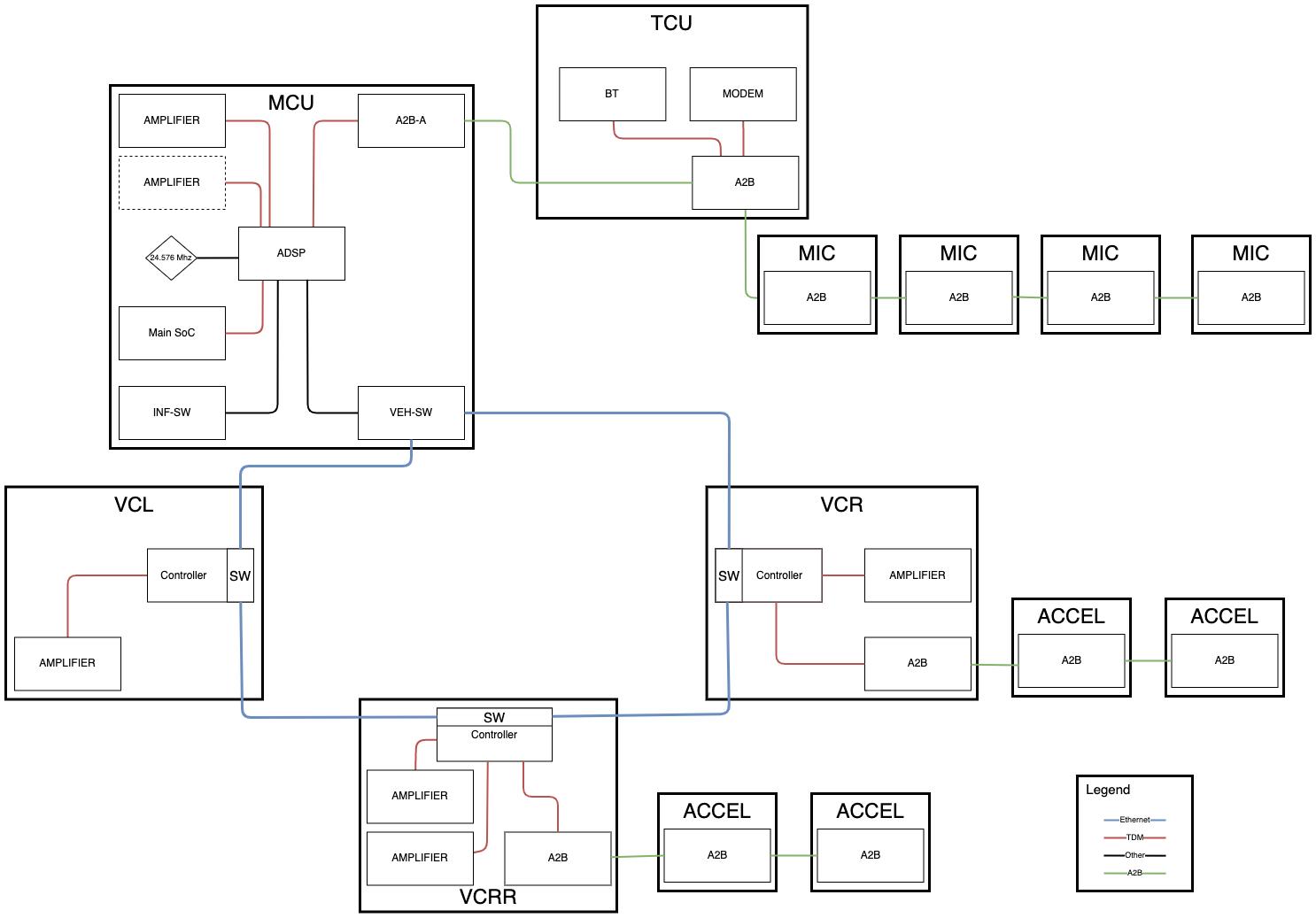
A high-level architecture diagram of the inputs and outputs to the ADSP is shown in the image below. The audio data will be encoded by the ADSP and transported over Ethernet on the Etherloop.
There are three Automotive Audio Bus (A2B) networks:
-
A2B-A:
- Connects the ADSP, TCU, front seat microphones, and A-Pillars' microphones in a daisy chain.
- The ADSP is the host controller, and the TCU and microphones are the subordinate nodes.
-
VCRIGHT A2B:
- Connects the VCRIGHT to the front left suspension accelerometer and front right suspension accelerometer in a daisy chain.
- The VCRIGHT is the host controller, and the accelerometers are subordinate nodes.
-
VCREAR A2B
- Connects the VCREAR to the rear left suspension accelerometer and rear right suspension accelerometer in a daisy chain.
- The VCREAR is the host controller and the accelerometer are the subordinate nodes.
 |
|---|
| Audio Components Block Diagram |
Speakerslink
Cybertruck contains 17 speakers. The speakers are connected to the amplifier chipsets in the vehicle controllers or in the car computer on the infotainment board. Two of those speakers are dedicated to the pedestrian warning system, one of which is the Superhorn.
The Superhorn combines the function of the traditional "trumpet" horn and pedestrian warning speaker into one cohesive component. For more information about the PWS speakers (including the Superhorn), refer to the Safety and Restraints section.
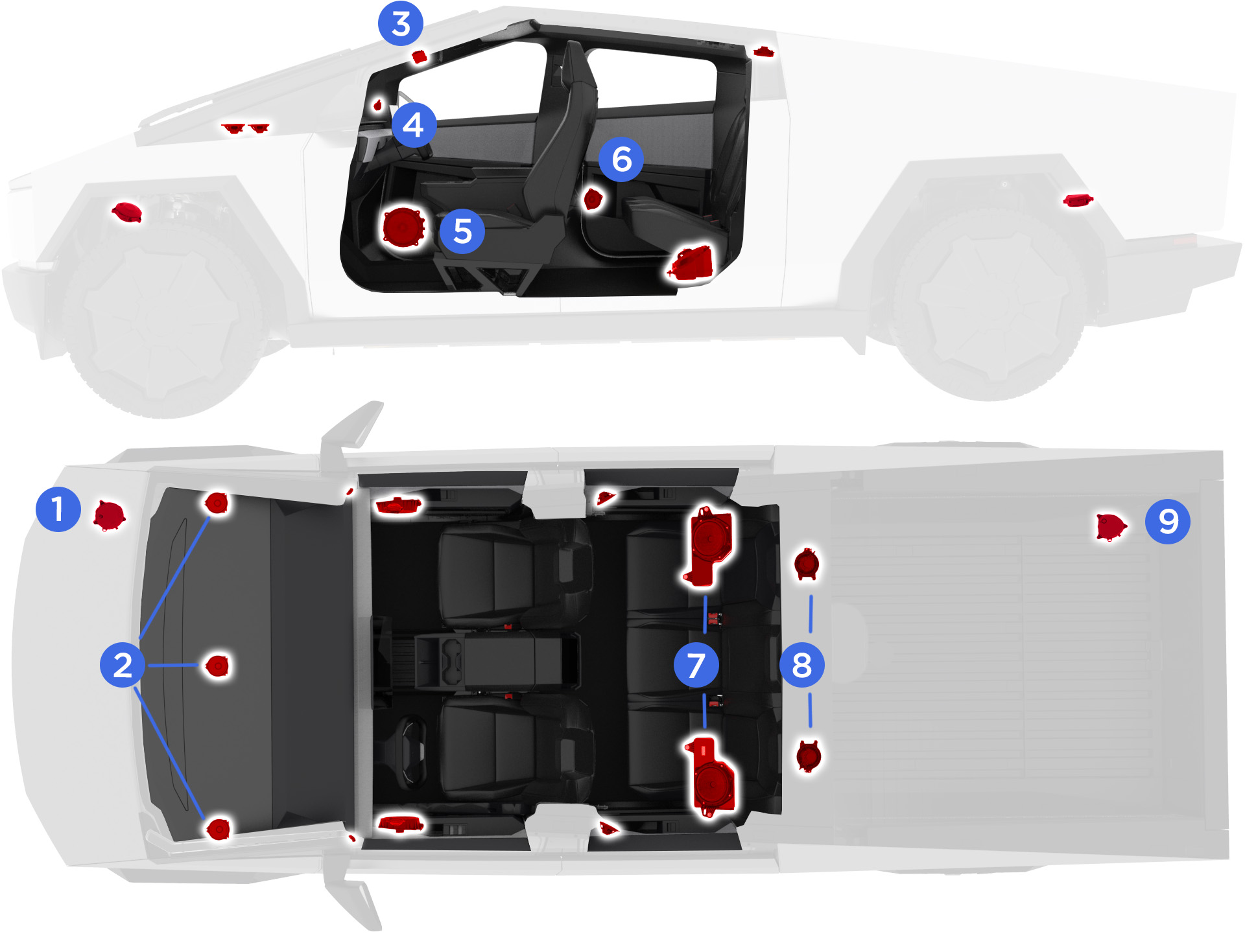
The diagram below outlines the placement of the speakers.
 |
|---|
| Speaker Locations |
Speaker Listlink
While referencing the image above, the list of speakers can be seen in the table below:
| Reference No. | Quantity | Image | Size | Type | Frequency Response | Impedance | Location | Amplifier |
|---|---|---|---|---|---|---|---|---|
| 1 | 1 | Mono | - | Superhorn | - | 2Ω | Front fascia | MCU |
| 2 | 3 | Left, Center, Right | 100mm | Full-range | 200Hz-13kHz | 3Ω | Instrument Panel | MCU |
| 3 | 2 | Left and Right | 60mm | Full-range | 200Hz-13kHz | 4Ω | A-Pillar Upper Trim | LEFT and RIGHT CONTROLLERS |
| 4 | 2 | Left and Right | 25mm | Tweeter | 3.5kHz-20kHz | 4Ω | A-Pillar Upper Trim | LEFT and RIGHT CONTROLLERS |
| 5 | 2 | Left and Right | 200mm | Woofer | 50Hz-200Hz | 4Ω | Front Door Closures | LEFT and RIGHT CONTROLLERS |
| 6 | 2 | Left and Right | 100mm | Full-range | 200Hz-13kHz | 3Ω | Rear Door Trim | LEFT and RIGHT CONTROLLERS |
| 7 | 2 | Left and Right | 200mm | Subwoofer | 50Hz-200Hz | 5Ω | Below second row | REAR CONTROLLER |
| 8 | 2 | Left and Right | 100mm | Full-range | 200Hz-13kHz | 3Ω | Rear Wall | REAR CONTROLLER |
| 9 | 1 | Mono | - | Rear PWS | - | 4Ω | Rear Diffuser | REAR CONTROLLER |
Amplifier Chipsetslink
The vehicle contains 4 amplifier chipsets:
- 1 is located on the Infotainment Board (MCU amplifier chipset).
- 1 is located in the LEFT Controller.
- 1 is located in the RIGHT Controller.
- 2 are located in the REAR Controller.
Together, these amplifier chipsets drive the 17 speaker sound system and 2 PWS speakers. They convert the audio signal from digital formats to analog format. They amplify the signal according to the speaker specification. The amplifier chipsets also have the advanced load diagnostic features, which means they are capable of detecting an open load, shorted load, short-to-battery, or short-to-ground conditions for the speaker connections and report it to the ADSP.
MCU Amplifier Chipsetlink
The Media Control Unit (MCU) has one speaker amplifier chip that accounts for a total of four channels. The layout is listed below:
- Channel 1: Pedestrian warning speaker (Superhorn) at the front.
- Channel 2: Right full-range speaker on the Instrument Panel.
- Channel 3: Left full-range speaker on the Instrument Panel.
- Channel 4: Center full-range speaker on the Instrument Panel.
LEFT Controller Amplifier Chipsetlink
The LEFT Controller has one speaker amplifier chip that accounts for a total of four channels. The layout is given below:
- Channel 1: Left woofer on the front door closure.
- Channel 2: Left full-range speaker on the rear door trim.
- Channel 3: Left tweeter speaker on A-Pillar upper trim.
- Channel 4: Left full-range speaker on A-Pillar upper trim.
Right Controller Amplifier Chipsetlink
The RIGHT Controller has one speaker amplifier chip that accounts for a total of four channels. The layout is given below:
- Channel 1: Right woofer on the right door closure.
- Channel 2: Right full-range speaker on the rear door trim.
- Channel 3: Right tweeter speaker on A-Pillar upper trim.
- Channel 4: Right full-range speaker on A-Pillar upper trim.
Rear Controller Amplifier Chipsetlink
The REAR Controller has two speaker amplifier chip that accounts for a total of eight channels. The layout is given below:
-
REAR Amp 1:
- Channel 1: Spare channel.
- Channel 2: Rear right full-range speaker on the rear wall.
- Channel 3 and 4: Right rear subwoofer below the second row seats.
- The rear woofers are driven by 2 channels, so they have a higher power output.
-
REAR Amp 2:
- Channel 1 and 2: Left rear subwoofer below the second row seats.
- Channel 3: Rear pedestrian warning speaker.
- Channel 4: Left full-range speaker on the rear wall.
Audio Over Etherlooplink
The digital audio data of the speakers are encoded by the ADSP and transported to the vehicle controllers through the vehicle Etherloop. The microcontroller in the vehicle controllers is responsible for decoding the Etherloop data to the format for the speaker amplifier chipset. It is also responsible for synchronizing the playback of audio signals. There are 2 types of protocol present in the audio Etherloop traffic: Generalized Precision Time Control Protocol (gPTP) and Audio Video Transport Protocol (AVTP). The ADSP is the gPTP clock master.
Audio traffic on Ethernet consists of data to the speakers, data from microphones, accelerometers tuner.
The Etherloop audio nodes are:
- ADSP
- Left Controller
- Rear Controller
- Right Controller
Audio data travels counterclockwise, starting from ADSP > LEFT Controller > REAR Controller > RIGHT Controller. This means that, for example, if the LEFT controller was unresponsive, there will be no audio coming from the speakers that are connected to the LEFT, REAR, and RIGHT controllers.
Automotive Audio Bus (A2B)link
Cybertruck contains 3 A2B audio buses:
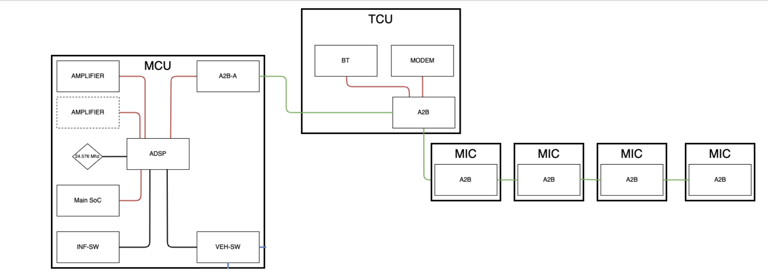
- A2B-A:
- Connects the ADSP, TCU, front seat microphones, and A-Pillars' microphones in a daisy chain.
- The ADSP is the host controller, and the TCU and microphones are the subordinate nodes.
 |
|---|
| A2B-A |
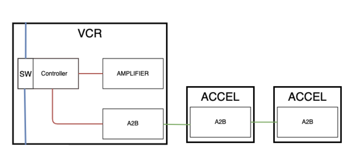
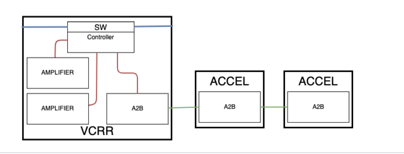
- VCRIGHT A2B:
- Connects the VCRIGHT to the front left suspension accelerometer and front right suspension accelerometer in a daisy chain.
- The VCRIGHT is the host controller, and the accelerometers are subordinate nodes.
 |
|---|
| Right Controller A2B Network |
- VCREAR A2B:
- Connects the VCREAR to the rear left suspension accelerometer and rear right suspension accelerometer in a daisy chain.
- The VCREAR is the host controller, and the accelerometer are the subordinate nodes.
 |
|---|
| Rear Controller A2B Network |
If these alerts are persistent, then there is an issue with the A2B network:
- ADSP_a2baDiscoveryFailed
- ASDP_a2baFault
Radio Tuner / Antennalink
Cybertruck's tuner will support FM/HD radio. It is located above the driver in the overhead console. It will have two antennas. Both are mounted on the roof glass. One antenna is connected directly to the tuner on the driver's side. The other antenna is connected to an antenna amplifier on the passenger side. There is no support for XM or AM frequencies. The tuner connection bypasses VCRIGHT and connects to the Ethernet switch on the car computer. It is not part of the Etherloop.
The tuner has the capability of detecting opens and short circuits between the antennas. There are log lines in the tunaman directory that will signify the open or short.
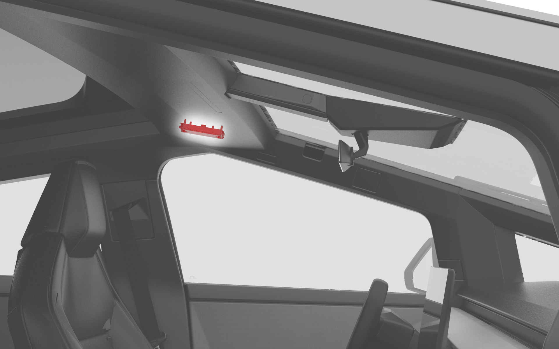 |
|---|
| Tuner |
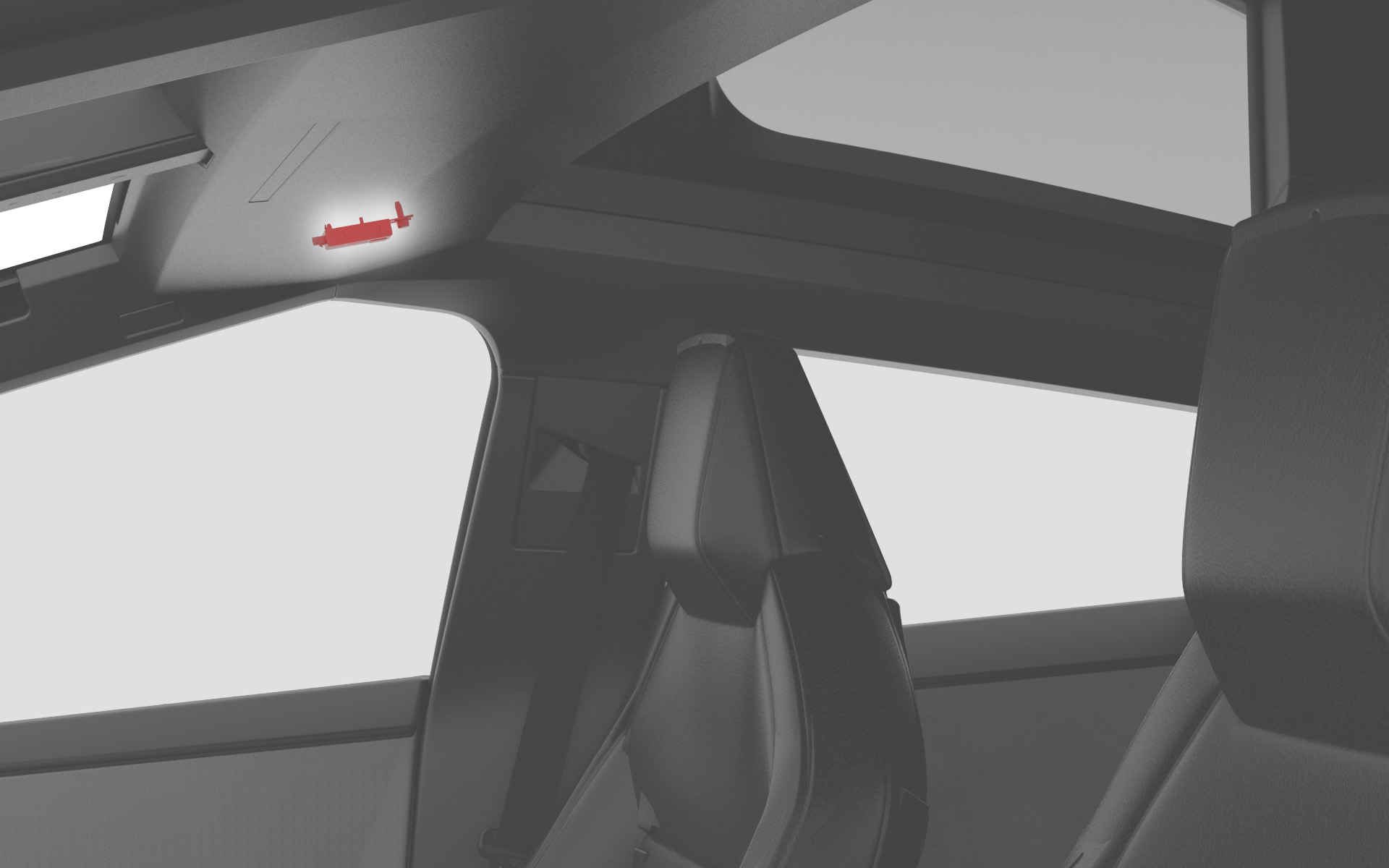 |
|---|
| FM Antenna Amplifier |
Microphoneslink
Cybertruck contains two headliner microphones and two seat microphones. The two headliner microphones are used for Telephony (calls and voice commands).
The telephony microphones are located on the A-pillar and the front seats headrests. They are connected to the Telematics Control Unit (TCU), which is connected to the MCU through the infotainment Ethernet switch and A2B.
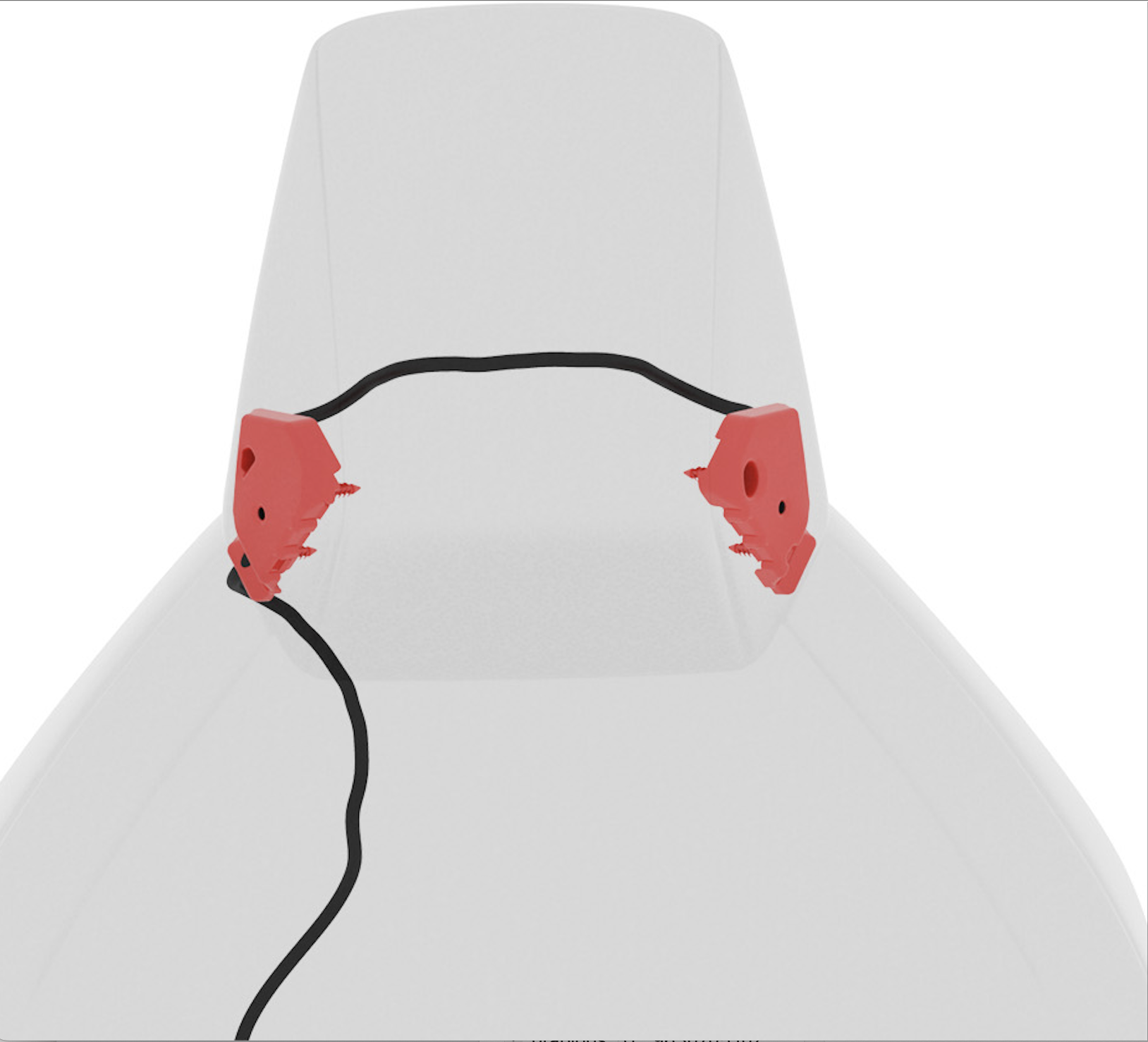 |
|---|
| Front seat microphones |
Voice Signal Processinglink
Voice processing in performed by the ADSP in the main Infotainment Board. Voice analog signals are generated by the microphones and converted to digital. Then, they go to TCU, and eventually, to ADSP through the A2B bus. The eCall and Bluetooth voice signals will be sent back to the TCU after the telephony processing. Voice command will be sent to the main SoC.
Audio Serviceabilitylink
The following components are replaceable for the audio system:
- All speakers
- Radio Tuner
- Antenna amplifiers
- TCU
The following components are not replaceable for the audio system:
- ADSP - part of the Infotainment Board
- MCU amplifier - part of the Infotainment Board
- Etherloop amplifier - part of the vehicle controller
- Seat microphones - part of the seat assembly