Brake Systemlink
Last updated: May 11, 2024
Overviewlink
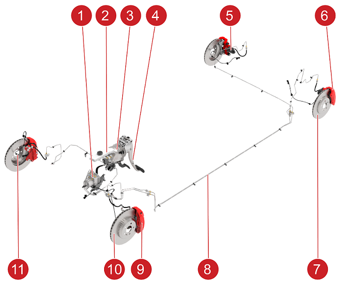
The 2024+ Model 3 brake system is a hydraulic based brake system, consisting of four brake calipers actuated by an electromechanical brake booster and an Electronic Stability Program (ESP) system. The rear brake calipers have an integrated Electronic Park Brake (EPB) motor mounted to each caliper for the electronically actuated parking brake.
 |
|---|
| 1. ESP Unit Assembly 2. Brake Fluid Reservoir 3. Electromechanical Brake Booster 4. Brake Pedal Assembly 5. EPB Motor 6. Rear Brake Caliper 7. Rear Brake Rotor 8. Rear Hydraulic Brake Lines 9. Front Brake Caliper 10. Front Brake Rotor 11. Wheel Speed Sensor |
| Brake System, Overview |
Depending on the configuration, the brake system will have the following:
Base Package:
- Grey calipers
- Internally ventilated cast iron rotors
Performance Package:
- Red calipers
- Lightweight two-piece rotors for enhanced performance and thermal capacity
Brake System Overviewlink
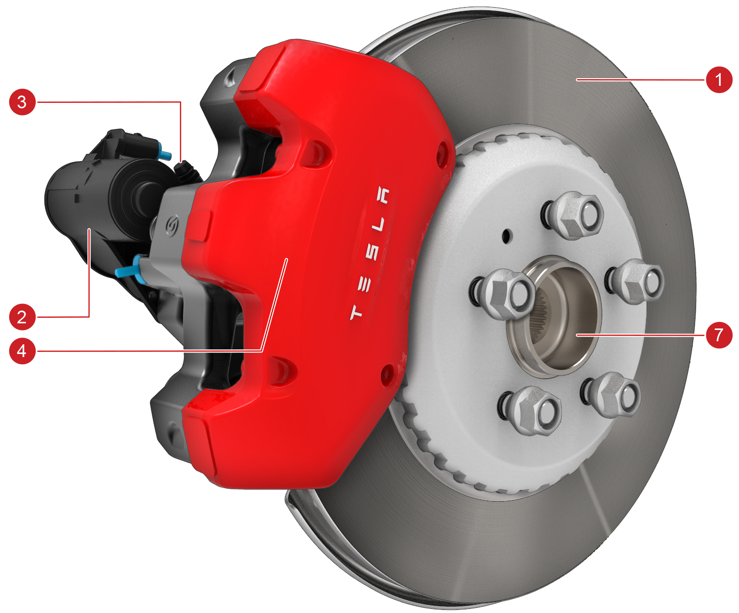
Front Brake Caliperslink
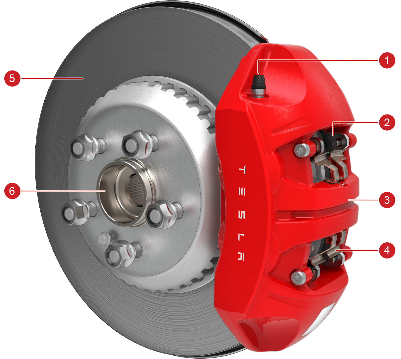
The front brake system uses a mono-block aluminum four-piston design fixed caliper with dual bleed nipples.
 |
|---|
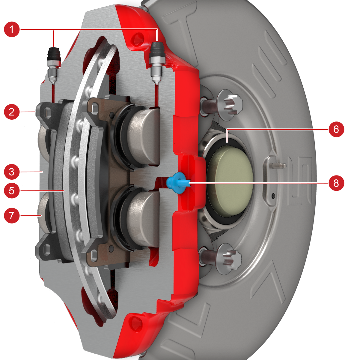 |
| 1. Brake Fluid bleed nipples 2. Brake Pad 3. Brake Caliper Body 4. Brake Pad anti-rattle shim 5. Brake Rotor 6. Hub (incorporates Wheel Speed Sensor Tone Ring) 7. Brake Piston (x4) 8. Brake Flexible Pipe connection |
| Front Brake |
Rear Brake Caliperslink
Mando/ZF Rear Brake Caliperslink
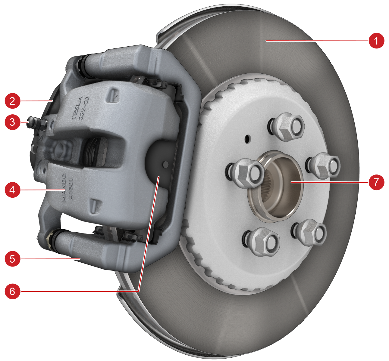
The Mando/ZF rear brake system uses a single piston sliding caliper with an integrated EPB with a single bleed nipple.
 |
|---|
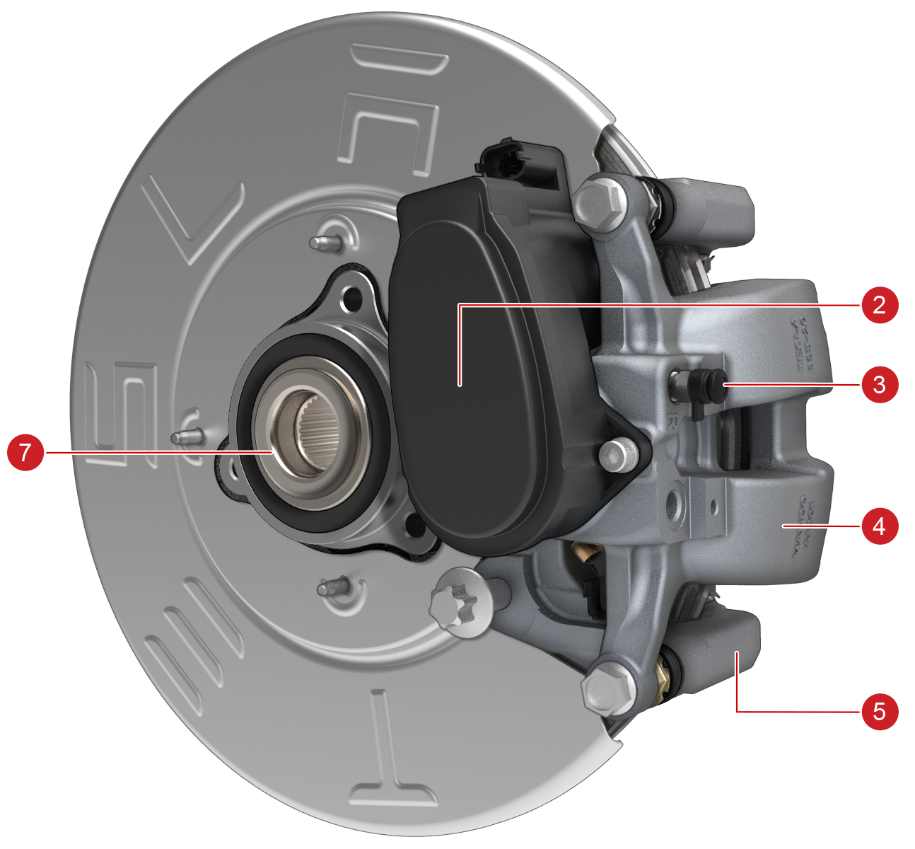 |
| 1. Brake Rotor 2. Electronic Park Brake (EPB) 3. Single Bleed Nipple 4. Brake Caliper 5. Brake Caliper Carrier 6. Brake Pad 7. Hub (incorporates Wheel Speed Sensor Tone Ring) |
| Mando Rear Brake |
Brembo Rear Brake Caliperslink
The Brembo rear brake system uses a single piston sliding caliper with integrated EPB and a single bleed nipple.
 |
|---|
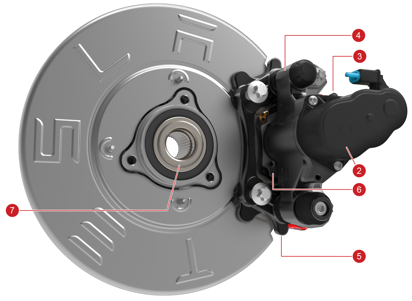 |
| 1. Brake Rotor 2. Electronic Park Brake (EPB) 3. Single Bleed Nipple 4. Brake Caliper Body 5. Brake Caliper Carrier 6. Brake Pad 7. Hub (incorporates Wheel Speed Sensor Tone Ring) |
| Brembo Rear Brake |
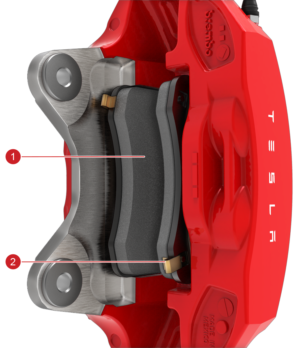
Brake Padslink
The brake pads consist of non-asbestos, organic friction material bound to a steel backing plate located between the caliper pistons and the rotor. They are equipped with wear indicators which are thin metal strips attached to the brake pad that squeal as they rub against the rotor when the pad wears down. This squealing sound indicates that the brake pads have reached the end of their service life and require replacement.
 |
|---|
| 1. Brake Pad 2. Wear Indicator |
| Brake Pad and Caliper |
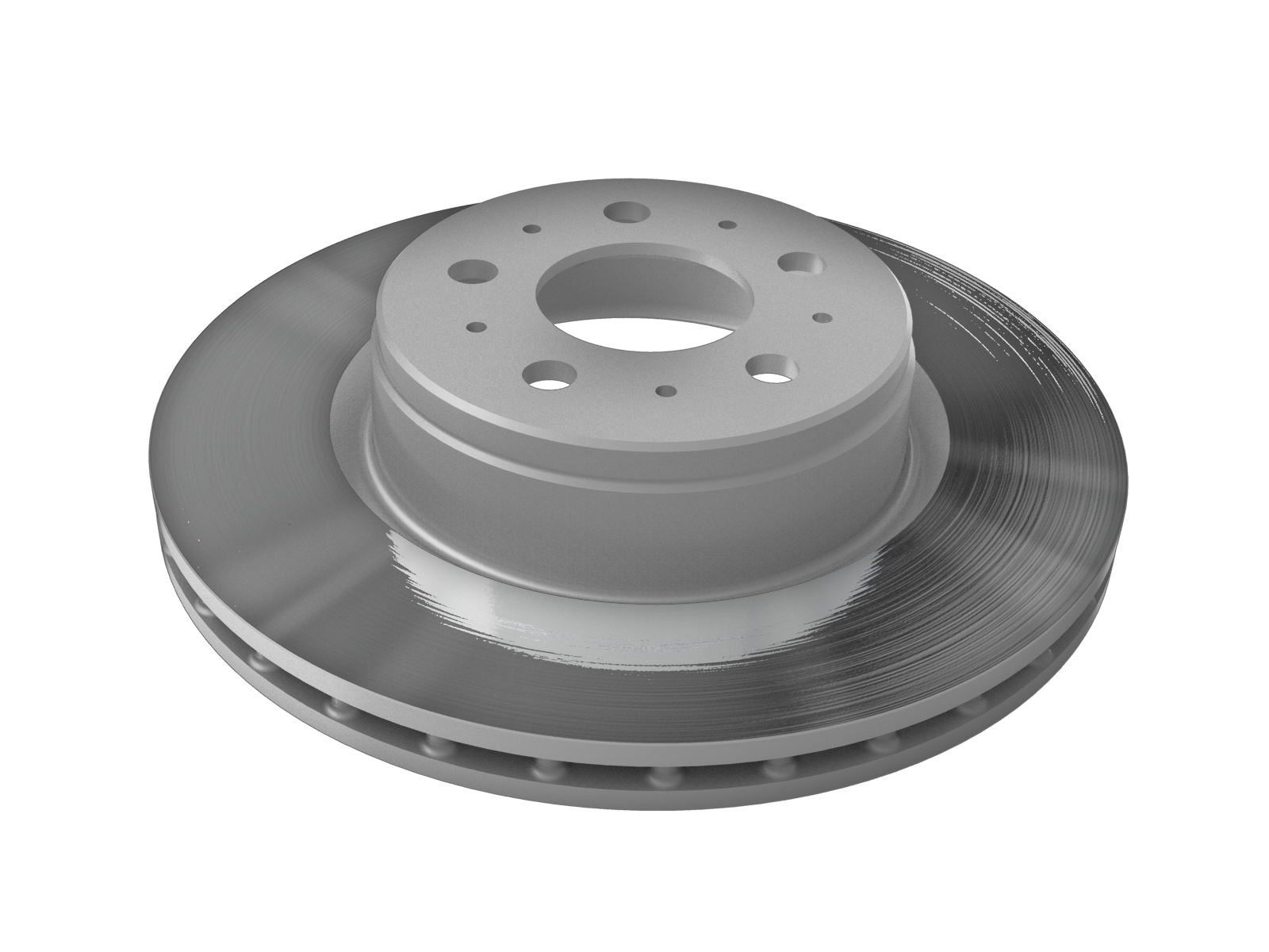
Brake Rotorslink
The brake rotors of base package have a single-piece, internally ventilated, cast iron structure treated with a hardening process to improve corrosion protection and wear resistance, making these non-serviceable. The brake rotors of performance package have a lightweight two-piece rotors for enhanced performance and thermal capacity. Brake rotors have a minimum thickness level specified in the Service Manual.
 |
|---|
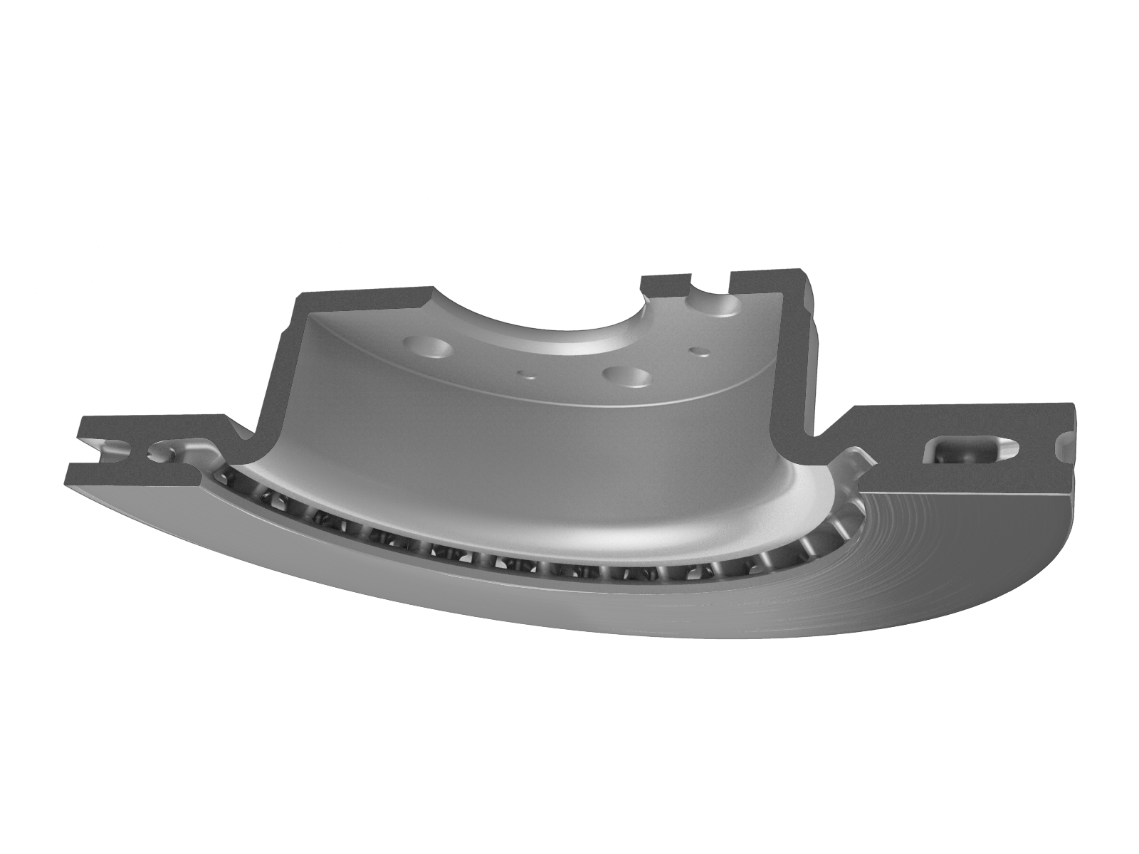 |
| Base Rotor |
 |
|---|
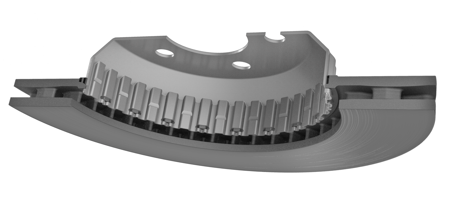 |
| Performance Rotor |
Electronic Park Brakelink
The Electronic Park Brake (EPB) system is integrated into the rear foundation brake calipers and is not separately serviceable.
The EPB system is comprised of an EPB drive unit, brake caliper, piston assembly, brake pad assembly, and two electronic control units (ECU). The EPB control units are integrated into the left vehicle controller (VCLEFT) and right vehicle controller (VCRIGHT). VCLEFT and VCRIGHT control their corresponding EPB motor.
The parking brake can be engaged by multiple methods:
- By pressing and holding either the P button on the Gear Strip located on the left side of the touchscreen or the P button on the front overhead module.
- Touching the Parking Brake button under Controls > Safety with feet pressed on the brake pedal.
If the parking brake is applied, the RED parking brake will light up on the touchscreen.

Additionally, the parking brake is automatically applied when the driver exits while the vehicle in Reverse, Neutral or Drive. But the RED parking brake will not light up.
!!! Note The EPB will be applied but the RED parking brake indicator will NOT light up if the P button is short pressed.

If a fault has been detected with the EPB, the YELLOW parking brake will light on the touchscreen with a fault message.
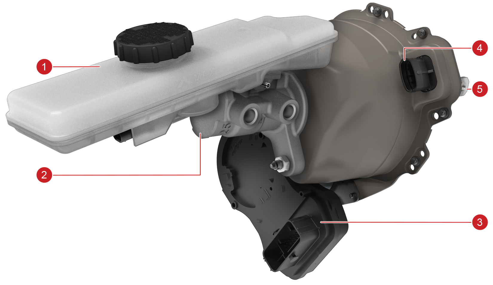
Electromechanical Brake Booster (iBooster)link
 |
|---|
| 1. Brake Fluid Reservoir 2. Tandem Master Cylinder (TMC) 3. Booster Powerpack ECU 4. Booster Gear Housing Assembly 5. Input Rod |
| iBooster |
The electromechanical brake booster is the 2nd generation iBooster. This iBooster has reduced box volume with a more compact design and reduced weight compared to traditional vacuum booster due to plastic material use and simplified gear housing. The iBooster is a vacuum-free electromechanical actuated system which is an integral part of the brake system. The control principle behind the iBooster is similar to that of vacuum brake boosters: in vacuum brake boosters, a valve controls the air supply to provide a boost to the force applied from the driver‘s foot. With the iBooster, the actuation of the brake pedal is detected via an integrated differential travel sensor and this information is sent to the control unit. The control unit determines the control signals for the electric motor, while a three-stage gear unit converts the torque of the motor into the necessary boost power. The power supplied by the booster is converted into hydraulic pressure in a tandem master cylinder. Additionally, the iBooster can build up pressure independently, without the need for the driver to apply the brake pedal. Compared with ESP, the required braking pressure is built up three times more quickly. This offers significant benefits for automatic emergency braking systems.
If the iBooster suffers an irrecoverable fault, such as disruption of supply-power, the driver can still brake unhindered since the driver's brake energy is transmitted mechanically through the booster to the Tandem Master Cylinder (TMC). Additionally, The ESP system will detect a booster fault and generate additional brake force to aid the driver by using its own hydraulic pump (normally used for stability and traction control events). The brake force is metered proportional to the measured upstream hydraulic pressure from the TMC to allow reasonable modulation of the driver's brake force. During a booster fault, a pumping noise will be heard and pedal pulsations will be felt through the brake pedal. This is the intended backup operating mode and it allows for much greater vehicle deceleration to be achieved than by the driver alone. This function is called the Hydraulic Boost Compensation (HBC).
Brake Fluid Reservoirlink
The brake fluid reservoir, mounted on top of the TMC, is a specially formed, clear, plastic fluid container designed to fill to the necessary brake fluid volume. If the brake fluid level is too low, the brake fluid reservoir, which houses a fluid level indicator, will set a RED warning light on the touchscreen and will log an alert in the log data. If case of sensor fault or low brake fluid is detected, ESP will degrade its vehicle stability functionality in order to avoid pump actuation with absence of brake fluid.

Warning
Only Tesla-approved brake fluid is permitted in the brake system. The use of any other unapproved fluid might result in performance degradation or component damage. Do not use fluid from unsealed containers as it might have absorbed moisture from the atmosphere.
Booster Assemblylink
Warning
- No 3rd party modification is permissible.
- Foreign magnetic fields must be kept away from the ECU at all times.
- All parts are non-serviceable.
The booster assembly itself can be broken down into several key functional areas to aid service and troubleshooting discussions:
Powerpacklink
Consists of the ECU and motor housing. All of the electronic controls are located within the black plastic ECU housing. The housing is permanently attached to the booster motor housing and is non-serviceable. The 12V-brushless Direct Current motor is located in the cylindrical steel housing fastened to the booster assembly. Motor rotation is measured using a rotational hall-effect sensor. There is one electrical interface on the ECU housing to connect to the vehicle.
Gear Housinglink
The primary booster mechanical components are located inside the steel housing. The internal components are physically separate from the master cylinder, brake fluid volume, and external environment. This is a clean zone–no foreign contaminants, such as dirt, liquid, solvents, or lubricants, are permitted to enter the housing. Translation of the motor shaft rotation to linear motion is done by a gear-set inside this housing. A mechanical device to enable the driver to modulate brake force is packaged with the transmission. Located in the gear housing is the Differential Travel Sensor (DTS). The DTS is shielded from magnetic interference by the steel gear housing.
Input Rodlink
The input tie-rod is the mechanical link between the brake pedal arm and booster internal mechanism. It is connected to the pedal arm by a clevis and pin. It enters the booster housing through rubber bellows, which are extended through the entire booster through another tie-rod to rigidly couple with the TMC. The input tie-rod is very sensitive to all mechanical loading while not mounted. Extreme care should be taken when handling the booster while it is not fully assembled in the vehicle to avoid permanently damaging the booster mechanism.
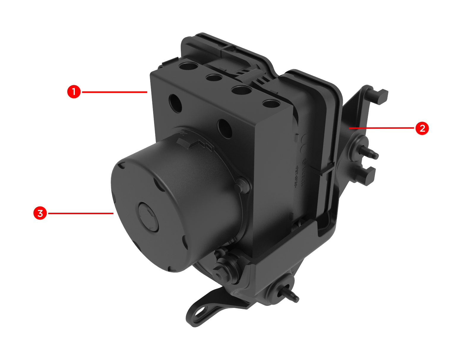
Electronic Stability Program Unitlink
 |
|---|
|
| ESP Unit |
Normal Brakinglink
The iBooster detects the driver’s brake request by an integrated Pedal Travel Sensor and this information is sent to the integrated control unit. The control unit operates the electric motor while a two stage gear unit converts the motor torque into the necessary longitudinal boost force. The force supplied by the booster and the driver is converted into hydraulic pressure in a conventional tandem master brake cylinder, which is the farthest upstream element of the “wet” hydraulic system. This is then distributed into the rest of the hydraulic system via the ESP unit.
The TMC consists of two floating hydraulic pistons in series. Each piston has one hydraulic inlet, from the brake fluid reservoir, and one hydraulic output routed to the ESP unit.
When the brake pedal is released, the springs in the master cylinder return the master cylinder pistons to the rest position. Brake system pressure is relieved, the caliper pistons retract, and the brake pads no longer apply a braking force to the rotors.
Electronic Stability Programlink
The ESP hydraulic control unit is separate from the iBooster and the calipers in the hydraulic circuit. This allows for the control unit to serve as a redundant brake actuation system in case of iBooster faults.
The ESP function assists the driver in maintaining control of the vehicle during cornering. The ESP differs from conventional Anti-lock braking systems (ABS) or Traction Control (TC) by using the yaw rate and acceleration sensor information in addition to the four wheel speed sensors (hall-effect sensors), which are located on the four wheel hubs and provide the wheel speed signal for each wheel.
The ESP calculates the intended path of the vehicle based on the driver’s inputs (from a steering angle sensor) and compares it to the measured rate of turn of the vehicle from the yaw rate sensor.
The ESP monitors for understeer or oversteer events during cornering. In the case of understeering, braking the rear inside wheel results in a positive yaw torque that helps the vehicle turn into the corner. During oversteering, braking the front outside wheel results in a negative yaw torque that steers the vehicle out of the corner and helps the rear axle regain traction. If the vehicle path deviates from the driver’s path, the ESP briefly applies the brakes at individual wheels to help steer the vehicle back to the intended path. The ESP also controls and limits motor power to the extent necessary to support lateral tire grip during cornering.
The ESP works on all road surfaces and weather conditions to help utilize all available road force to keep the vehicle stable. However, the ESP cannot evade the laws of physics and does not prevent loss of control if a driver carries excessive speed into a corner. Furthermore, the ESP only assists the vehicle to follow the path the driver is steering. The ESP does not prevent the driver from steering a vehicle off the road.
The ESP also operates as an ABS, which adjusts the maximum brake pressure transmitted to the wheels, preventing loss of road-holding under all tire and road conditions caused by wheel locking. The system has been designed to integrate, but not replace, the normal mechanical braking system.
The ESP controller constantly monitors and compares signals received from the four speed sensors. When the brake is applied and the ESP detects a wheel is decreasing speed in relation to the other wheels and that it is about to lock, the ESP modulator reduces the brake pressure at that wheel to prevent wheel locking. This alteration of brake pressure can be felt as a pulsing sensation through the brake pedal. This demonstrates that the ESP is operating and is not a cause for concern. As soon as the wheel speed becomes stable, the ESP controller increases brake pressure, thereby maintaining optimal braking force at all times. The ESP control system performs these adjustments several hundred times per second on each wheel independently. This enables the driver to achieve the highest brake force physically possible while maintaining vehicle stability and steering over any road surface.
The ABS indicator briefly flashes yellow on the touchscreen when the vehicle switches on. If this indicator lights up at any other time during the drive cycle, an ESP fault has occurred and the ESP is not operating. The braking system remains fully operational and is not affected by an ESP malfunction. However, braking distances might increase.

Traction Controllink
The traction control system constantly monitors the speed of the front and rear wheels. If a loss of traction is detected by analysis of the wheel speed sensors, the system minimizes wheel spin by controlling brake pressure using the ESP and motor torque using the drive inverter. By default, the traction control system is on. Under normal conditions, it should remain on to ensure maximum control of the vehicle.
The yellow indicator flashes on the touchscreen whenever the traction control system is actively controlling brake pressure and motor power to minimize wheel spin. If the indicator stays on, a fault is detected with the traction control system.

Hydraulic Fade Compensationlink
The Hydraulic Fade Compensation (HFC) is a function that increases the braking pressure when brake fade is detected by the ESP system. It looks at the pressure in the brake master cylinder, compares this to what is happening at the wheel, and uses the ESP pump to actively build pressure in the system up to ABS initiation levels. HFC will normally trigger when there is not enough friction between the brake pad and the rotor due to overheated, wet, or iced brake pads.
Alert ESP_a118_hfcActive will be recorded in the log data if HFC was active.
Hydraulic Boost Compensationlink
Hydraulic Boost Compensation (HBC) is a function that can provide a backup braking function by using the ESP hydraulic pump to generate the necessary brake pressure if the iBooster failed. This ensures redundancy and safety in case of an emergency. It looks at the IBST_hbcRequest signal sent by iBooster or detects an IBST MIA alert and then uses the ESP pump to actively build pressure in the system. ESP will create a pump noise when the brake pedal is applied, even if the vehicle is standstill. This is an intended noise that indicates the ESP is working as expected.
Alert ESP_a104_hbcEnabled will be recorded in log data if HBC was active.
Brake Disc Wipinglink
Brake disc wiping is an automatic assist program that maintains brake responsiveness in cold and wet weather conditions. Brake disc wiping repeatedly applies an imperceptible amount of brake force to clear away water on the brake disc surface. This ensures the brakes are responsive even during poor weather conditions.
Signals taken from the chassis and powertrain controller area networks (CAN) provide data on the following:
- Motor Torque
- Gear Selection
- Brake Pedal Activation
- Vehicle Speed
- Ambient Temperature
- Wiper State
- Battery Pack Temperature
This data is then compared to an internal algorithm to allow brake disc wiping activation command to the ESP. If any CAN faults or relevant signals are not available then the brake disc wiping request is void until the next key cycle.
The ESP will cause a pump noise when the brake disc wiping is triggered. This is an intended noise which means brake disc wiping is working as expected. Signal EPBL_brakeDiscWipeRequest and alerts ESP_a122_bdwActive will be recorded in log data if brake disc wiping was active.
Emergency Brakinglink
The emergency brake or dynamic brake can be actuated by holding the gear selector parking brake button. The touchscreen will display a visual warning and sound a chime. This is used in emergency situations in the event of the normal braking system encountering a malfunction like total brake fluid loss. The P button needs to be pressed until the desired reduction of speed has been obtained or until a complete stop.
An emergency brake request will cause the EPB to apply while the vehicle is moving.
Alerts EPBR_a180_dynamicActive and/or EPBL_a180_dynamicActive will be recorded in the log data if emergency braking was active.
Controlled Deceleration via Park Brakelink
Controlled Deceleration via Park brake (CDP) can provide a backup braking function by using the ESP hydraulic pump to generate the necessary hydraulic pressure to stop the vehicle if the brake pedal failed. This ensures redundancy and safety in case of an emergency. It looks at the EPBL_cdpRequest and VCLEFT_cdpRequestState signals sent by VCLEFT, VCFRONT_brakeFluidLevel sent by the front vehicle control unit (VCFRONT), and uses the ESP pump to actively build pressure in the system. The ESP will make a pump noise when CDP is triggered. This is an intended noise which means CDP is working as expected. If the CDP was active, signal ESP_cdpStatus ==ACTUATING_EPB_CDP will be recorded in log data.
In all regions, pressing the P button will now quickly ramp out drive torque to 0 Nm. On release of the P button, drive torque will slowly ramp back in.
Note
In China only, if the acceleration pedal is pressed in excess of 90% for at least two seconds and speed is in excess of 30km/h, pressing the P button will remove the drive torque until the acceleration pedal is released for at least half a second. During the time drive torque is removed, the UI will display a large indicator instructing the driver to release the acceleration pedal.
Automatic Emergency Brakinglink
Warning
Automatic Emergency Braking is designed to reduce the severity of an impact. It is not designed to avoid a collision.
Warning
The brake pedal moves downward abruptly during automatic braking events. Always ensure that the brake pedal can move freely.
When Automatic Emergency Braking applies the brakes, the touchscreen will display a visual warning and sound a chime. The driver might also notice an abrupt downward movement of the brake pedal. The brake lights turn on to alert other road users that the vehicle is slowing down.
Automatic Emergency Braking logic is performed by the Driver Assistance System. For more details on how this feature operates, see the Automatic Emergency Braking section of the Driver Assistance System Hardware 4.0 Theory of Operation.
Automatic Emergency Braking does not apply the brakes or stops applying the brakes when:
- The driver turns the steering wheel sharply.
- The driver presses and releases the brake pedal while Automatic Emergency Braking is applying the brakes.
- The driver accelerates hard while Automatic Emergency Braking is applying the brakes.
- The obstacle is no longer detected ahead.
Automatic Emergency Braking is automatically enabled. To disable it for the current drive, use the touchscreen:
Controls > Autopilot > Automatic Emergency Braking
Vehicle Holdlink
Vehicle Hold can continue to apply the brakes even after the foot brake has been released. After coming to a complete stop, press the brake pedal again until the touchscreen displays the Vehicle Hold indicator light to enable Vehicle Hold.
The driver can then release the brake pedal and remain stopped, even on a hill.
 This indicator displays on the touchscreen whenever Vehicle Hold is actively braking.
To disengage Vehicle Hold, press the accelerator pedal or press and release the brake pedal. Shifting into Neutral also disengages the Hill Hold Function.
Note
Vehicle Hold shifts into Park after approximately 10 minutes of use or detection of Driver Leaving the vehicle.
Dynamic Brake Lightslink
Driving over 50 km/h (31 mph) and applying the foot brake forcefully (or if Automatic Emergency Braking engages) will cause the brake lights to flash quickly to warn other drivers of the rapid deceleration. The hazard warning lights also flash until the accelerator is used or hazard button is pressed.
Note
Dynamic brake lights will not flash whilst in Track Mode.
Slip Startlink
To allow the wheels to spin at a limited speed, the driver can enable Slip Start. Slip Start can be enabled at any speed. However, it is less effective at higher speeds.
Under normal conditions, Slip Start is off by default. Enable it only in circumstances when deliberate wheel spin is required:
- Starting on a loose surface like gravel or snow.
- Driving in deep snow, sand, or mud.
- Rocking out of a hole or deep rut.
To activate Slip Start, use the touch screen menu:
Controls > Driving > Traction Control > Slip Start
The touchscreen displays an alert message when Slip Start is enabled.

Slip Start is not available whilst using Traffic Aware Cruise Control. If Traffic Aware Cruise Control is activated whilst vehicle is in Slip Start the system will revert back to normal traction control conditions.
Note
Slip Start is automatically disabled the next start cycle.
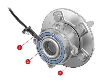
Wheel Speed Sensorlink
 |
|---|
| 1. Wheel Speed Sensor 2. Sensor tone ring integrated into wheel bearing 3. Hub |
The wheel speed sensors provide the digital wheel speed signals to the ESP modulator. A wheel speed sensor is installed in each wheel hub unit. The sensing element is situated to align with the magnetic sensor tone ring, which is integrated with the inboard bearing seal. Each seal contains the magnetic elements arranged in pole-pairs that make up the tone ring. Only one side of the bearing contains the integrated tone ring.
As the wheels rotate, the pole-pairs in the seals induce sinusoidal voltage fluctuations in the wheel sensors (Hall Effect sensors) that are converted into square wave signals. The signal frequency is proportional to the speed of each wheel.
The wheel speed sensors are active sensors. They output a current-based signal that has been converted from analogue form and processed in the sensor unit before being sent to the ESP control unit. This ensures that disturbances and errors in the raw Hall Effect signals are not passed to the ESP processor. The pulse width carries further direction and diagnostic information and is not proportional to vehicle speed.
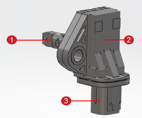
In order to support Adaptive Damping, an integrated sensor is introduced for each of the wheels in 2024+ Model 3 Performance. This integrated wheel speed sensor has the traditional hall-based output that will continue to route directly to the Electronic Stability Program (ESP), and it also adds a 3-axis accelerometer that will communicate acceleration data through the Automotive Audio Bus (A2B) interface to the microcontroller in the right vehicle controller (VCRIGHT).
 |
|---|
|
| Integrated Wheel Speed Sensor and Accelerometer |
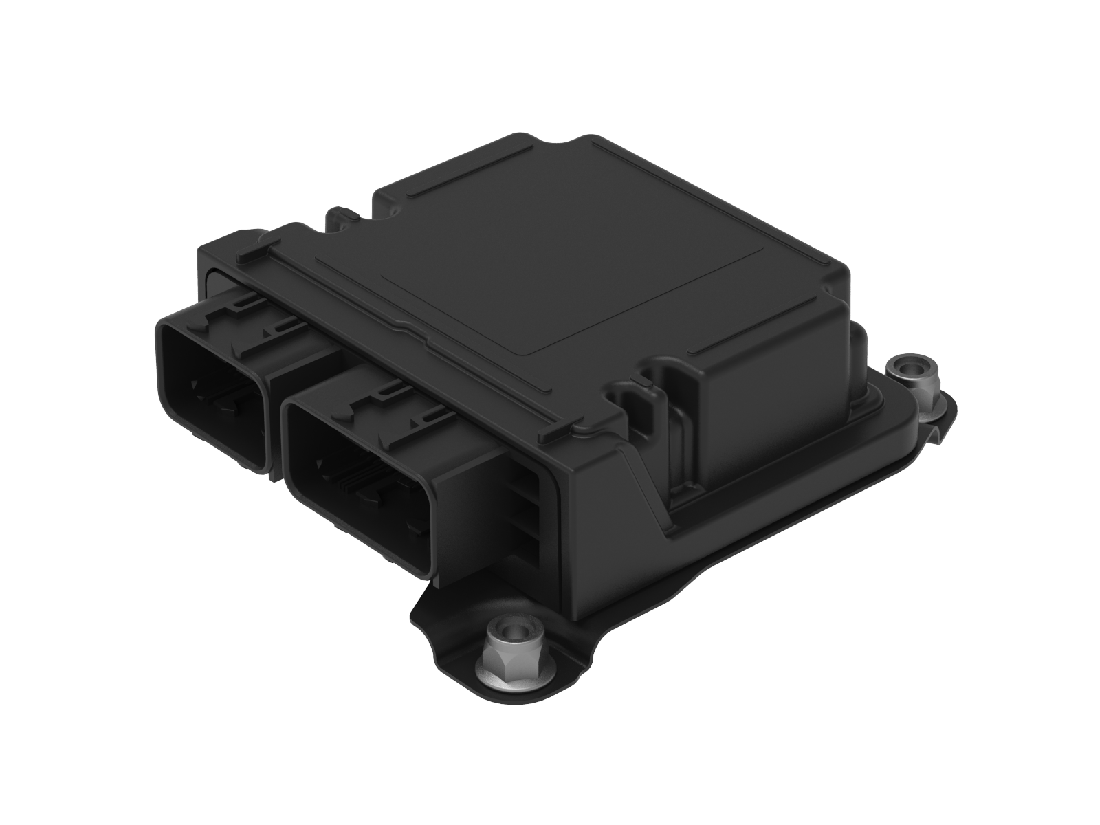
Inertial Measuring Unitlink
 |
|---|
| Restraint Control Module (with integrated inertial measuring unit) |
The Inertial Measurement Unit (IMU) is an electronic device that measures the yaw, roll, and pitch of the vehicle. This is integrated into the Restraints Control Module (RCM) and communicates with the ESP and iBooster over the chassis controller area network (CAN).
The sensor is used for ESP operation and measures the vehicle’s rotation around its vertical axis (yaw rate), while at the same time measuring the acceleration perpendicular to the driving direction. The ESP function uses the sensor inputs to detect the onset of side slip during cornering.
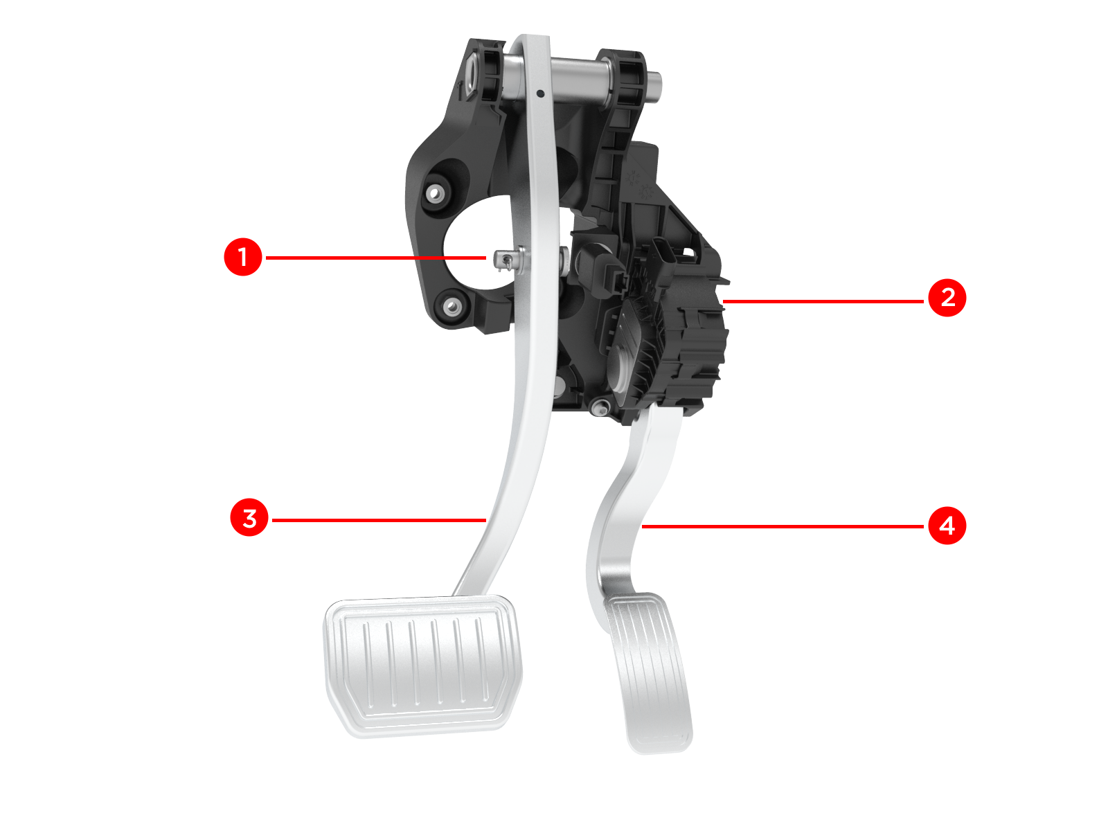
Pedal Assemblylink
 |
|---|
|
| Pedal Assembly |
The brake pedal and accelerator pedal form a single assembly. The brake pedal arm connects to the iBooster input rod using a clevis. The accelerator pedal assembly has a housing at its pivot containing an electromagnetic induction device to sense rotation. There are two circuits for redundancy.
System Faultslink
If the ESP system faults, normal braking is maintained. However, braking distances may increase and wheels may lock under heavy braking. The RED brake and/or YELLOW ABS fault indicator lights display in the instrument cluster along with a fault message.
|
|
|---|---|
| Touchscreen indicator that brake fluid level is too low | Touchscreen indicator that an ESP fault has occurred and the ESP is not operating |
If the vehicle power is interrupted and the Hydraulic Boost Compensation (HBC) is also not available, the iBooster is still able to provide a deceleration through a mechanical push-through, which provides a direct connection between the pedal and the master cylinder.