Connectivitylink
Last updated: October 20, 2023
Overviewlink
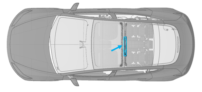
In 2024+ Model 3 vehicles, the Telematics Control Unit (TCU) replaces the connectivity card in the car computer. The TCU provides the functions of connecting to a cellular network, Wi-Fi network, and external Bluetooth (BT) devices. It combines the connectivity card (or modem card), Wi-Fi / BT module, and their antennas into a single assembly. The TCU is located in the B-headliner of the vehicle (see image below).
 |
|---|
| TCU Location |
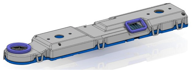
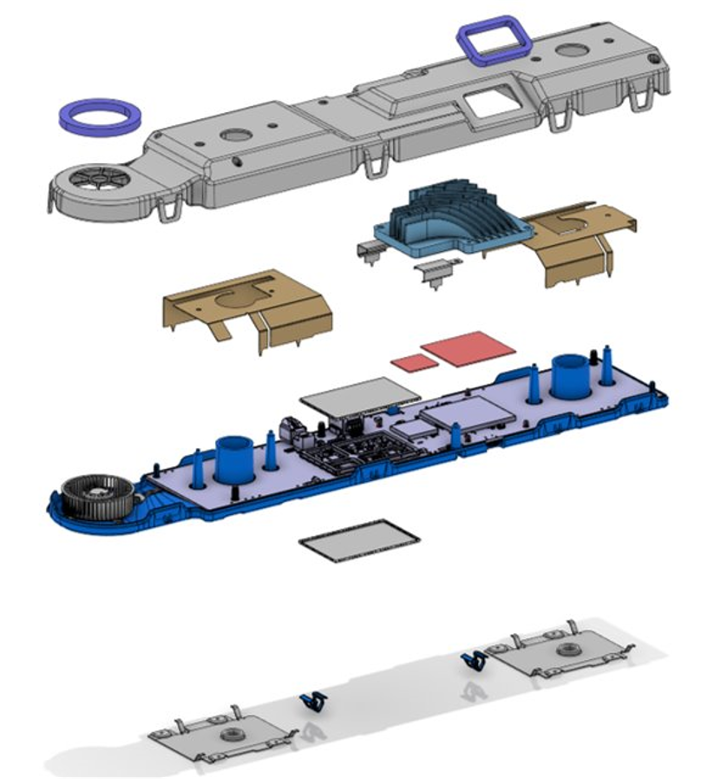
The TCU mainly consists of top and and bottom enclosures, a fan, a cast aluminum heat sink, and a printed circuit board assembly (PCBA).
 |
|---|
| TCU Assembly |
 |
|---|
| TCU (Exploded View) |
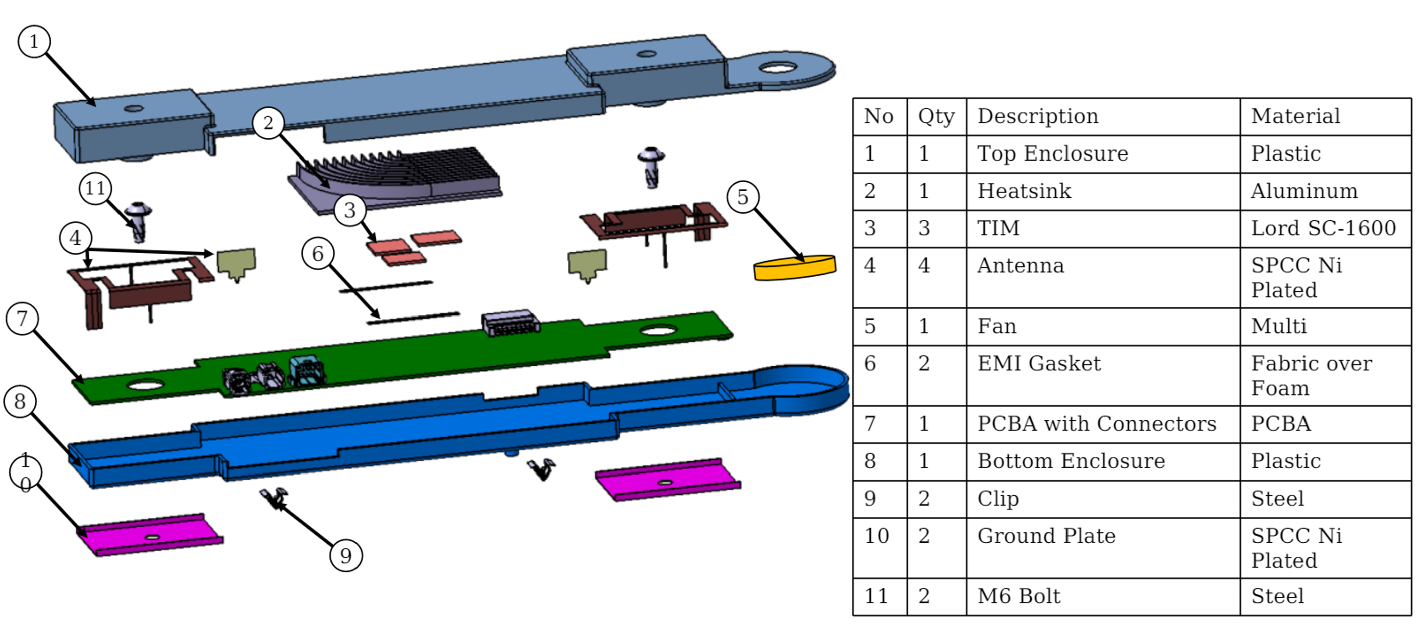
The fan housing is integrated into the TCU enclosure. The antenna is grounded to body-in-white through the ground plate. The heat sink is also used for shielding.
 |
|---|
| TCU Components |
System Architecturelink
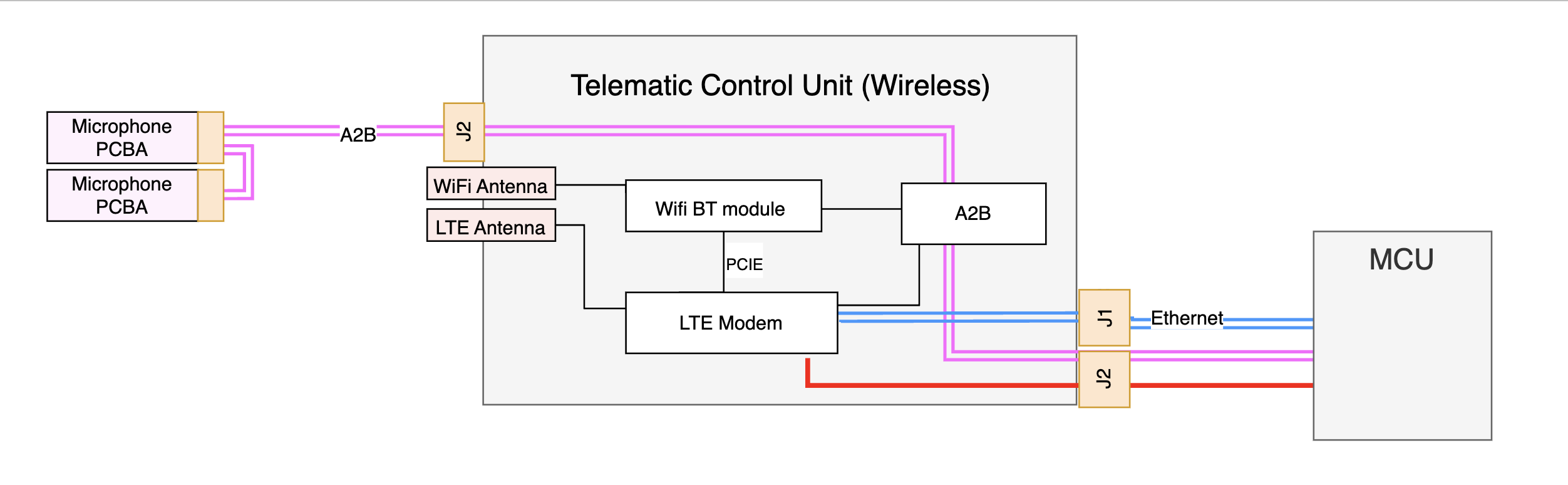
The TCU contains the LTE module, Wi-Fi / BT module, LTE and Wi-Fi / BT antenna, and Automotive Audio Bus (A2B) transceiver.
TCU is connected to the car computer through TC10 harness which carries all the data over ethernet protocol. This harness is used for data traffic between infotainment to modem module, Wi-Fi/BT module.
Connections out from the TCU are:
- 1 Ethernet connector to the Media Control Uni (MCU).
- 1 8-pin wire-to-board connector to the A2B and power from the MCU.
The system architecture of the TCU is shown in the image below.
 |
|---|
| TCU Block Diagram |
For legacy connectivity architecture, the LTE modem is located on a separately replaceable connectivity card attached to the Infotainment mainboard. Both the connectivity card and Wi-Fi / BT modules are on Infotainment main PCBA inside the car computer assembly. The two MIMO antennas are separate parts and communicate with the car computer through the RF coax cables.
The two images below compare the architectures of legacy and TCU connectivity.
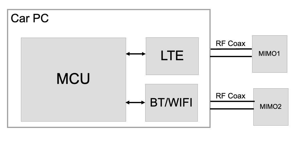 |
|---|
| Legacy Connectivity Architecture |
For TCU connectivity architecture, the modem and Wi-Fi / BT are taken out from infotainment mainboard and put into TCU PCBA, along with the MIMO antenna.
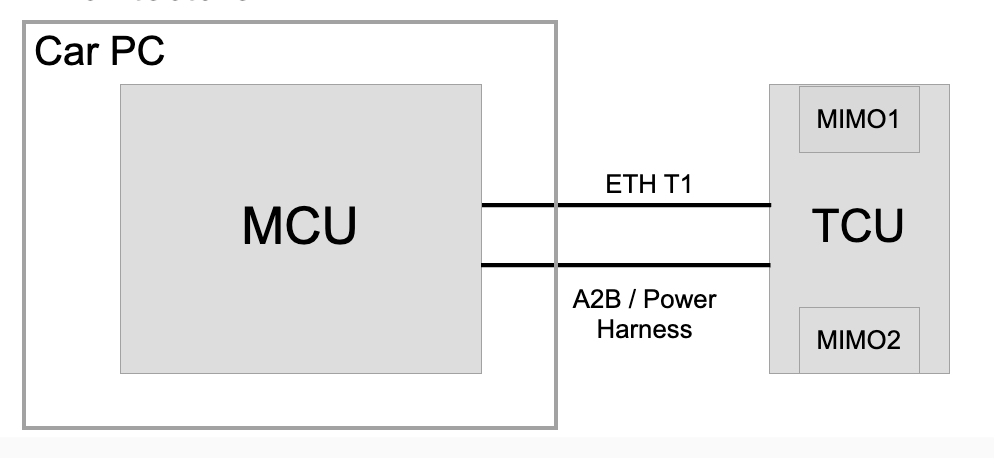 |
|---|
| TCU Connectivity Architecture |
TCU Components Breakdownlink
 |
|---|
| TCU PCBA |
Modem Modulelink
A single worldwide modem module variant is used in the TCU.
The TCU runs its own firmware package, and the package can be updated through the car computer updater and the TCU updater. The car computer updater communicates with the remote Tesla firmware server and controls the TCU updater. The TCU updater controls the firmware update procedure for the TCU.
The modem module is connected to the Wi-Fi / BT module through PCIe and UART. The modem is connected to the Infotainment ethernet switch in the car computer via the TCU ethernet switch. Data traffic flows between the car computer and the Wi-Fi / BT module through the modem module and the Infotainment ethernet switch.
SIM Cardlink
The TCU supports both embedded MFF2 SIM (eSIM) and external 2FF SIM (standard removable SIM). The SIM selection is controlled by the modem, and is configured by a configuration file stored in the AMD Ryzen system on chip (SoC). The selection of external SIM will be available for users by running action PROC_ICE_X_ENABLE-DISABLE-SIM-CARD.
An eSIM chip can store more than one profiles. The eSIM profile need to switch according to the carrier of the region. The eSIM profile selection is available for users by running action PROC_ICE_X_DUAL-BOOTSTRAP-E-SIM.
The external SIM reader slot is located on the TCU PCBA.
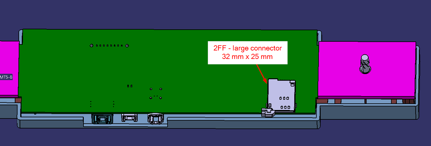 |
|---|
| TCU External SIM Card Reader Location |
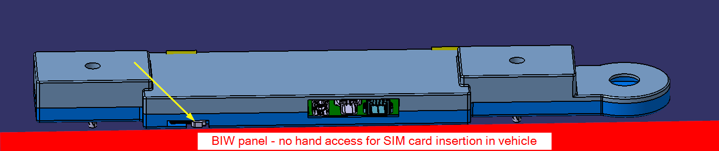 |
|---|
| TCU External SIM Card Insertion |
Wi-Fi and Bluetooth Modulelink
The data traffic flows from the Wi-Fi / BT module to the modem module, and then to the AMD Ryzen system on chip (SoC) on the car computer. Specifically, the Wi-Fi data flows through PCIe to the modem. The Bluetooth data and control traffic flow between Bluetooth chipset and modem module through UART. Modem and car computer exchange this data over ethernet using TC10 harness.
The Bluetooth voice traffic passes over the I2S interface on the A2B transceiver to the audio digital signal processor (ADSP) upstream in the car computer AMD Ryzen system on chip (SoC), or downstream to microphones. Bluetooth carries telephony audio via a hands-free-profile (HFP) and streams audio via A2DP.
Automotive Audio Bus Modulelink
The same Automotive Audio Bus (A2B) transceiver is used in the TCU as the one used in the infotainment board. The A2B module in the TCU is part of the A2B daisy chain. The A2B module in the infotainment board is the A2B primary, and the one in the TCU is the A2B secondary. The upstream of the daisy chain from the TCU is the Audio Digital Signal Processor (ADSP) on infotainment main board and the downstream are the microphones.
A2B is also used for module level control signaling between infotainment board and TCU. Infotainment computer can use this interface to reboot the TCU, read and write GPIO connected to Modem module, and determine which NAND (Primary or Recovery) to boot the TCU from.
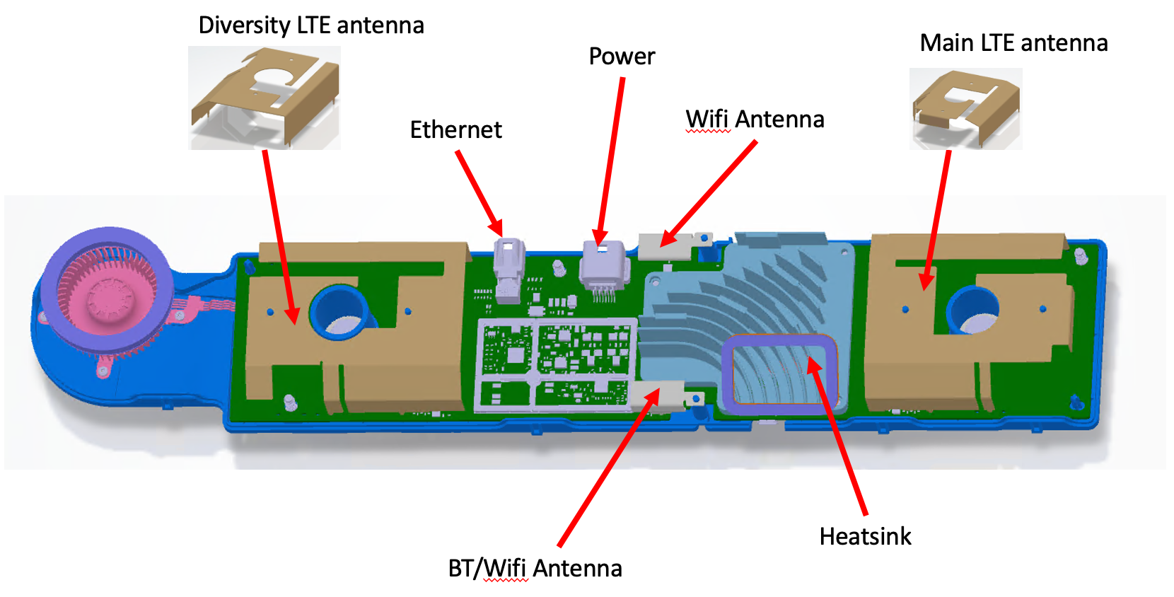
Antennaslink
The MIMO antennas in the TCU are integrated into the TCU PCBA and are not individually serviceable.
- 2 LTE antennas functioning as a 2x2 MIMO pair.
- One is main LTE antenna and the other one is the diversity LTE antenna.
- 1 dedicated Wi-Fi antenna supports the 2.4GHz and 5GHz Wi-Fi MIMO.
- 1 switched antenna supports either the 2.4GHz Bluetooth or 2.4GHz and 5GHz Wi-Fi MIMO.
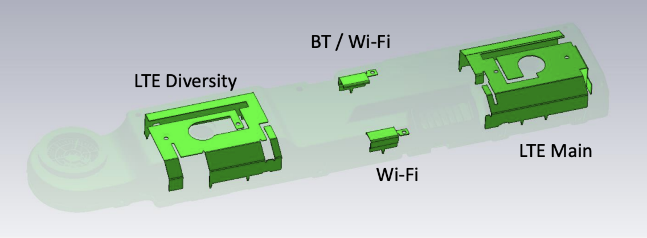 |
|---|
| TCU Antenna |
Interfaceslink
The TCU power is supplied by the infotainment mainboard through the same connector of the A2B bus.
- TCU is powered by MCU.
- A2B connects to upstream MCU board.
- A2B connects to downstream microphone board.
In addition to the functional modules, there is a GPIO expander chip in the TCU to control the TCU property. The GPIO expander chip can be configure by the A2B primary through the A2B bus. It is used to reboot the modem module, read and write the GPIOs, and determine which NAND (primary or recovery) to boot modem from. This serves as a control interface between infotainment board and the TCU.
The ethernet switch on the TCU board exists behind a physical layer transceiver referred to as “TCU PHY”. This is similar to how the Ethernet switch on the infotainment board in the car computer exists behind a physical layer transceiver referred to as “MCU PHY". The function is to establish communication between TCU and MCU. There is also a micro-USB port for debugging purpose.
Cooling Systemlink
With the TCU being located on the B-headliner where high ambient temperature is expected, there are multiple cooling methods are used:
- Dispensable Thermal Interface Material (TIM).
- Cast Aluminum heat sink is used for LTE modem and Wi-Fi / BT modules.
- Fan / blower is controlled by the modem module.
- Flow guides are designed as images below. Metal grill and foam (similar to what is used for speakers) are with the flow guides.
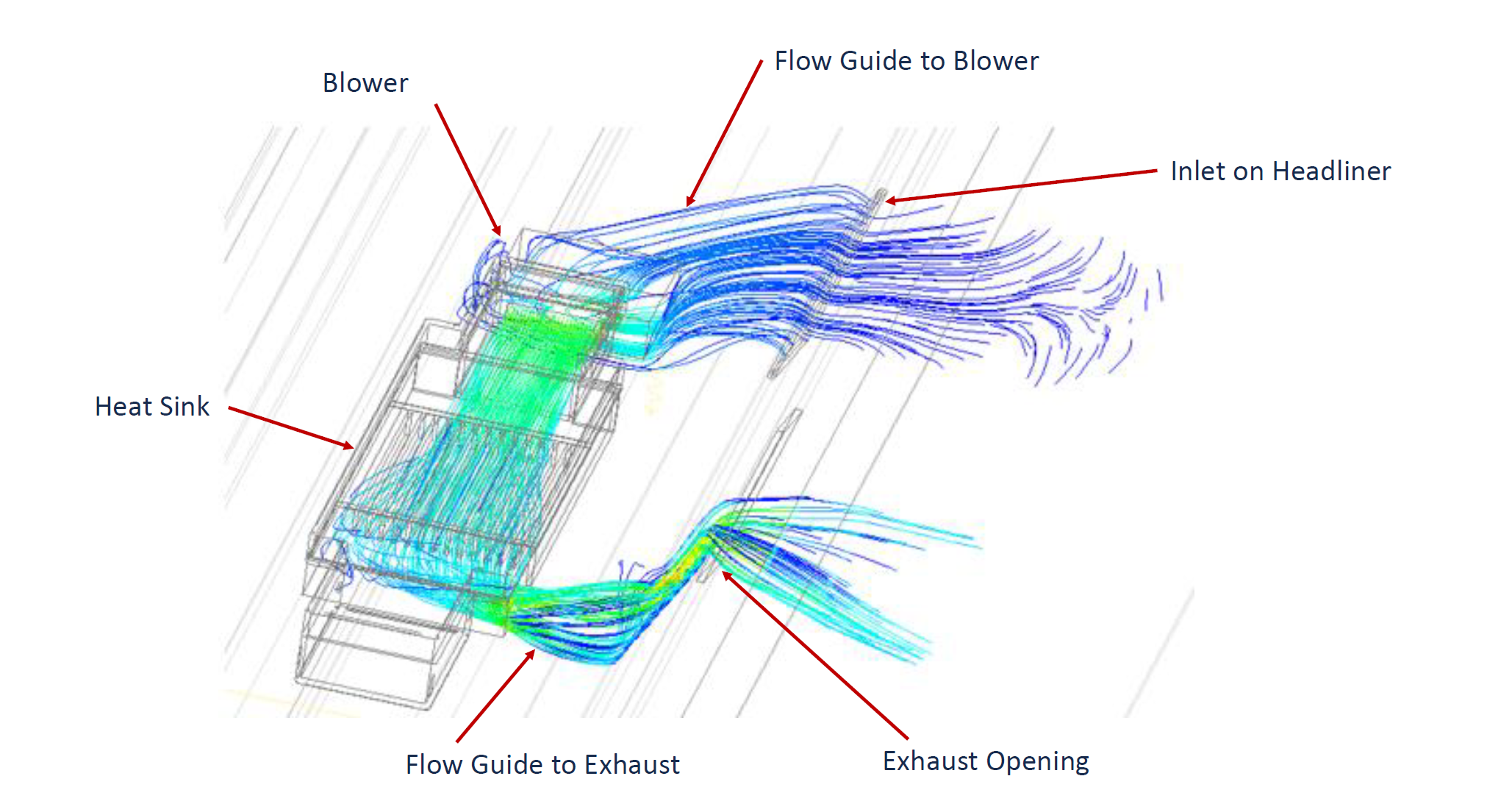 |
|---|
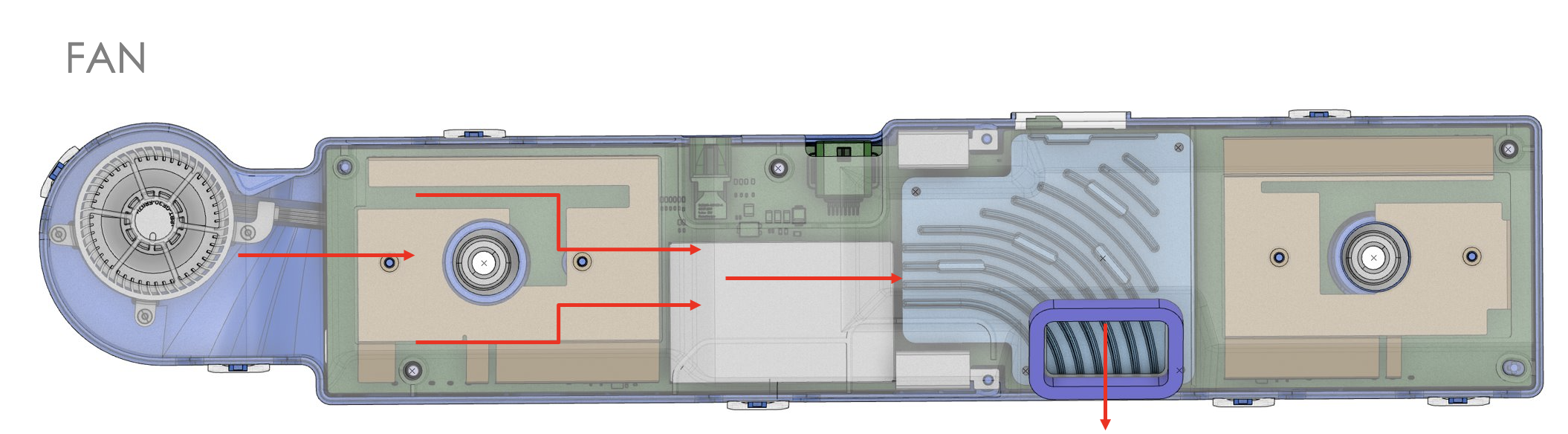 |
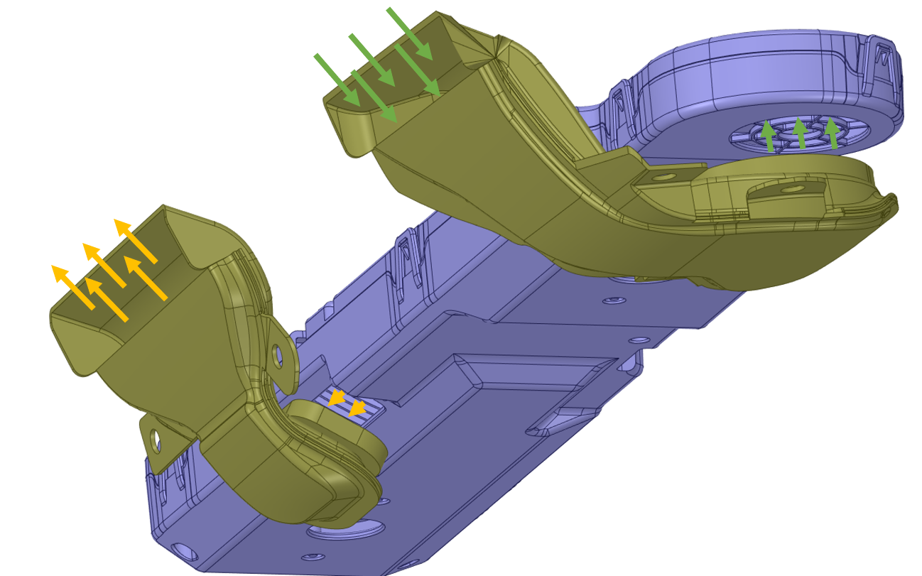 |
| TCU Thermal Fan Airflow |
A temperature sensor is located in the modem chipset and is used to read the temperature. The fan will be needed depending on the ambient and solar loading conditions, and the duty cycle will be controlled based on the following parameters:
- Temperature of the LTE and Wi-Fi / BT modules.
- Occupancy state of vehicle.
- If an occupant is detects in the vehicle and if the HVAC is running at a lower setting, the fan will run at a lower duty cycle due to the proximity of the fan to the driver's and/or passenger's ears.
- State of the HVAC Blower.
For low ambient temperature, the TCU module is expected to operate without needing the a fan. The TCU periodically wakes up, checks the temperature, and goes into sleep. If the temperature exceeds the threshold, then the fan will be turned on without waking up the MCU.
Connectivity Functionslink
The TCU provides cellular, Wi-Fi, and Bluetooth connectivity, and also E-call functionality.
Cellular Connectivitylink
The modem module of TCU is responsible for the cellular communication of the TCU. The control traffic of the modem is through the A2B bus and the data traffic is through the ethernet switch.
- Low-level firmware processes run in the modem, and are responsible for communicating with the cellular tower of the carrier.
- The cellular tower will register or unregister the modem depending on the information provided by the modem. The information includes the modem, SIM card identification, and the technology it supports.
- The cellular carrier may provide limited service (Roaming) if the SIM card ID does not matching its local market region.
- High-level firmware processes manage the Wi-Fi and Bluetooth connectivity.
The modem only supports LTE (or 4G) cellular standard or below.
Users with a physical connection to the vehicle can power cycle the modem chip and restart the software processes without rebooting the car computer and the rest of the TCU. However, users cannot access the low-level modem software in TCU directly.
Wi-Fi Connectionlink
The Wi-Fi software stack runs on the Wi-Fi module of the TCU. The data traffic flows from Wi-Fi module to the modem module and then to ethernet switch. The function of the Wi-Fi stack includes:
- Loading the Wi-Fi kernel module.
- Setting up the WLAN interface on the TCU.
- Enabling "wpa_supplicant" process so the TCU can resolve authentication to connect to a wireless access point.
- Running "DHCP" to get an IP address from the access point once connected.
- Running "DNSmasq" so the MCU can connect to TCU.
Connection management processes run on the AMD Ryzen system on chip (SoC) to control the Wi-Fi module, and includes:
- Health check for connectivity.
- Knowledge about Wi-Fi power state.
- Control of the Wi-Fi module power state and interfaces with TCU over a tcp socket.
Users with a physical connection to the vehicle can power cycle the Wi-Fi / BT chip and restart the AMD Ryzen system on chip (SoC) software processes without rebooting the car computer and the rest of the TCU. However, users cannot access the Wi-Fi stack software in TCU directly.
Bluetooth Connectionlink
Bluetooth media audio and control signals are sent via ethernet from the TCU to the MCU while Bluetooth telephony call audio is sent via A2B from and to the MCU.
Bluetooth A2DP audio is communicated to the MCU using the ethernet path and is used for streaming music from a connected Bluetooth device. HFP audio is used for hands-free calls and follows the I2S path from the BT module to the MCU over A2B. The eCall audio follows the I2S path from the LTE module to the A2B transceiver.
Users with a physical connection to the vehicle can power cycle the Wi-Fi / BT chip and restart the software processes without rebooting the car computer and the rest of the TCU.
E-Calllink
The voice signals are transferred from A2B microphones to the ADSP and then to then modem after telephony processing. The uplink voice signals are transferred from A2B microphones to the ADSP and then to then modem after telephony processing. Similarly, the downlink voice signals are transferred from the modem to the ADSP for processing, and then to the speakers over A2B.
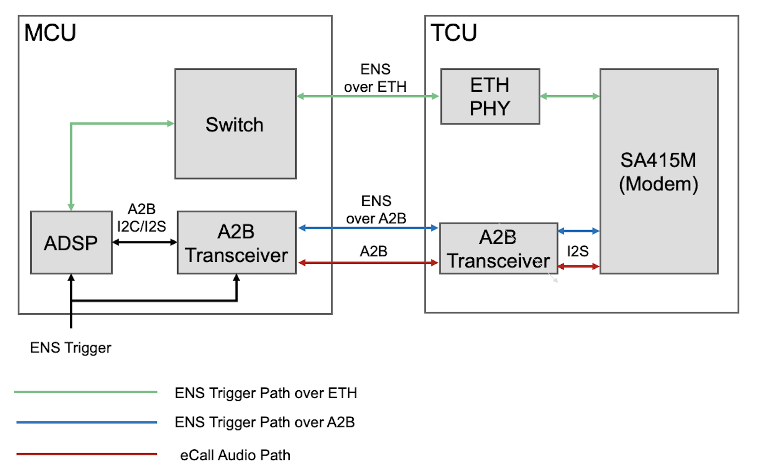 |
|---|
| TCU E-Call Architecture |
Wake Process Flowlink
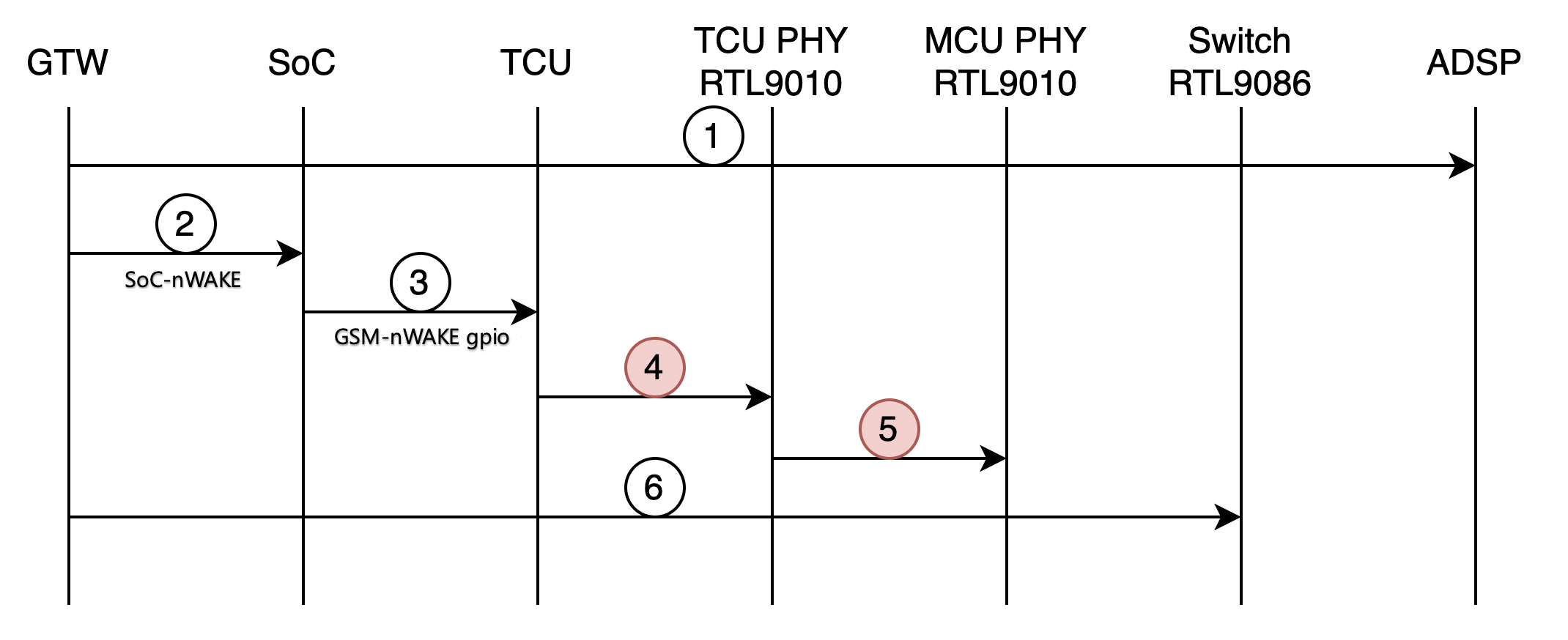
TCU runs in a low power sleep mode when the vehicle infotainment is not in use. The modem within the TCU is connected to the vehicle Gateway (GTW) via ethernet and sends a wake signal when an SMS message is received. The TCU SMS wake sequence is as follows (see image below):
- Modem receives an SMS.
- The TCU asks TCU PHY to wake up via local wake protocol (i.e. toggling the WAKE line of RTL9010 TCU PHY), but the TCU itself does not fully wake up.
- TCU PHY sends a remote wakeup via Wireless Uni-Protocol (WUP) to the MCU PHY.
- MCU PHY wakes up and pulls INH high, causing an interrupt on the Gateway and wakes the Gateway up.
- Gateway powers on ADSP.
- Gateway toggles SOC-nWAKE pin to wake SoC from S3 sleep.
- SoC wakes up TCU by toggling TCU's nWAKE GPIO via ADSP A2B.
- Gateway powers on switch.
- This can happen any time after Step 4 and can happen in parallel to those steps.
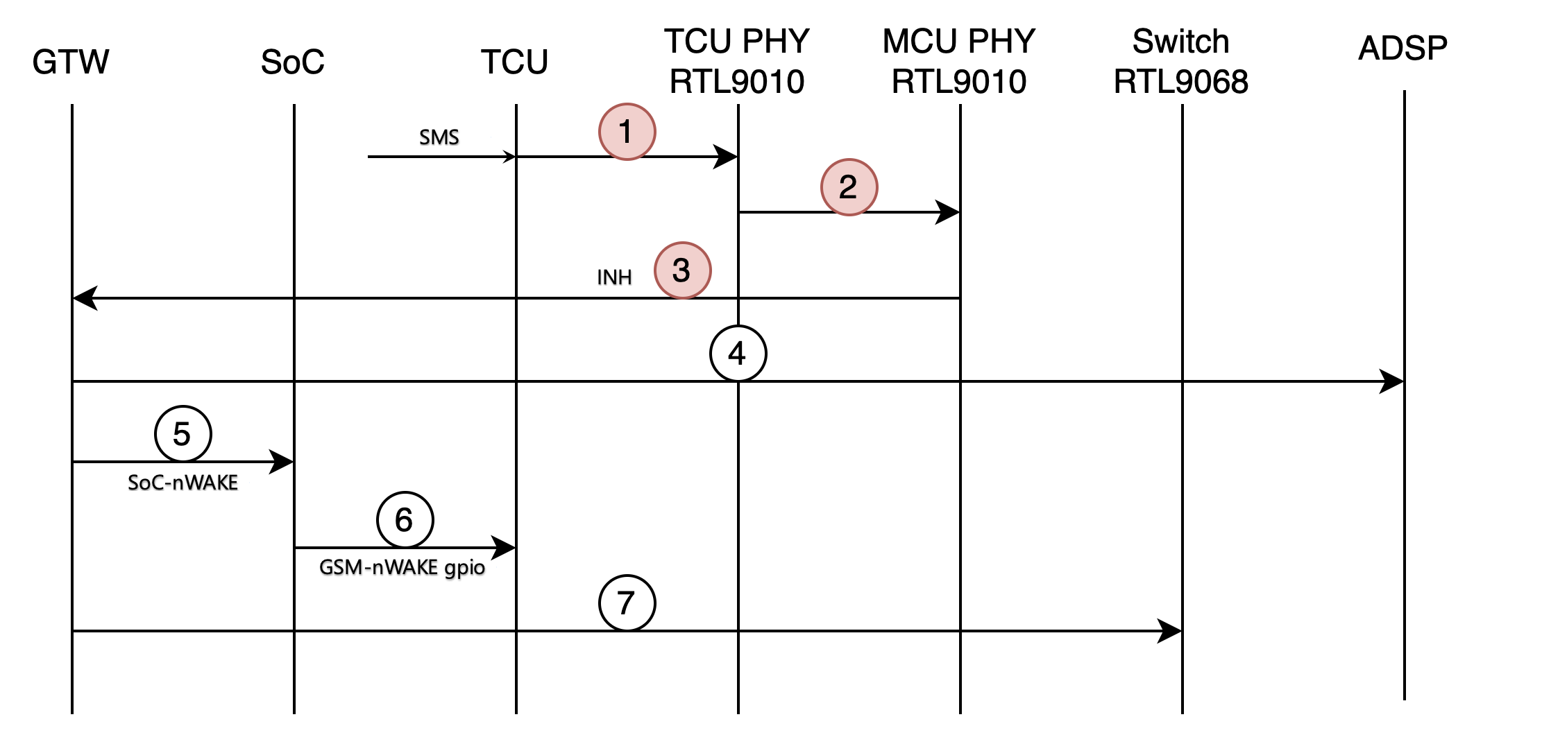 |
|---|
| TCU SMS Wake Sequence |
The TCU can also wake via a Controller Area Network (CAN) wake sequence, outlined below:
- Gateway receives a CAN wake (handle pull, charger, etc.) and powers on the ADSP.
- Gateway toggles SOC-nWAKE to bring SoC out of S3.
- SoC toggles nWAKE pin for TCU via ADSP A2B to being TCU out of sleep.
- TCU performs a local wake on the TCU PHY via local-wake pin of the TCU PHY.
- TCU PHY initiates a remote wakeup of MCU PHY by sending WUP.
- Gateway powers on the switch.
- This can happen at any time and can happen in parallel to other steps.
 |
|---|
| TCU CAN Wake Sequence |
Firmware Update and Recovery Modelink
The TCU runs its own firmware, and it has its own flash memory to store the package. The TCU boots from the flash memory in the unit and runs its own updater software. The TCU updater will update the firmware package in the flash memory when it receives the install command from the main infotainment updater. After a TCU replacement, a firmware reinstall must be performed for the firmware version of the TCU to be matched with that of the MCU.
Similar to the main infotainment system, the TCU will run into recovery mode if unable to boot a certain time. Users with a physical connection to the vehicle can determine the status of the updater by running action TEST-BASH_ICE_X_UPDATER-STATUS.
Serviceabilitylink
The status of the modem will be relayed to the AMD Ryzen system on chip (SoC) through the ethernet. User can read the status of the modem by running action TEST-BASH_ICE_X_LIST-DATAVALUES. In addition, a modem module health check can be run to verify whether the TCU hardware and firmware is running properly.
The Connectivity Panel on vehicles in Service Mode shows the status of both the cellular and Wi-Fi connection. It also lists available actions for hardware health checks.
The components of the TCU are not replaceable, except for the external SIM card. The TCU itself can be replaced.