Infotainmentlink
Last updated: October 03, 2024
Overviewlink
The Media Control Unit (MCU) is the main user interface in the Model X and houses critical control components, such as the Center Instrument Display (CID) Module and the Gateway. It sits in the middle of the instrument panel, angled towards the driver. The rear of the MCU contains connectors to other vehicle components, such as the CAN and audio systems.
- Additional Circuit Boards: Besides the motherboard, the MCU
contains other PCBs:
- Tegra Module
- Connectivity Daughter Board houses a cellular modem, GPS chips, and a SIM card slot. In premium MCUs, this board also contains the gyroscopic board.
- Parrot module provides Bluetooth and WiFi connection features.
- Audio daughter board
- 17 in touchscreen
- 2 fans
- MCU Chassis
- Grounding tab
- Grounding Strap
Center Instrument Display (CID)link
The CID module is the main component of the Infotainment system. It runs a customized Tesla UI built onto a Linux operating system. The CID and the operating system (OS) manage the:
- Touchscreen UI (Touch layer and display layer)
- USB bus
- Cell connectivity
- Bluetooth module
- Audio input/output
- The file system of the OS, where all the settings and driver profiles are saved
Gatewaylink
The Gateway is the automotive microcontroller on the motherboard. It connects to almost all the other devices on the motherboard and has a wide variety of functions, including:
- Power sequencing and voltage monitoring.
- CAN/LIN switch controller
- The Gateway is connected to all the CAN buses and routes all the messages among them. It also routes the messages from LIN bus to other buses.
- Manage other devices, such as Ethernet switches, temperature sensors, fans, SD cards, and flash updates.
Gateway vs CIDlink
The Gateway and the CID are two separate modules. They have their own tasks, but also communicate with each other over Ethernet and a serial port. The separation and independence allow the vehicle to keep driving while the infotainment system is experiencing any issues.
Gateway SD Cardlink
The Gateway comes with a SD card, where the vehicle log data is saved.
Connectivitylink
Cellularlink
All Model X vehicles come standard with a cellular connection. The components include:
-
Cellular modem
- Installed on the connectivity daughterboard and connects to the USB bus
- Contains an IMSEI (International Mobile Station Equipment Identity), a unique identifier for modems
- LTE modems are different for North America and EMEA / APAC
-
SIM Card
- Located in an external SIM extender under the MCU to provide easy access. The extender is behind the cubby under MCU.
- Each SIM card has an ICCID (integrated circuit card identifier), a unique identifier for SIM cards
-
Antennas
- Model X has two cellular antennas, one in each side mirror assembly. The antenna in the LH mirror is the primary antenna and the RH antenna is secondary antenna.
- The open circuit resistance of a cell antenna should be 10 KOhm.
-
Cell Antenna: The modem is able to detect antenna status. For 3G, only the primary antenna is displayed.
- APN: Access Point Name. A modem making a data connection must be configured with an APN to present to the carrier. The carrier will then examine this identifier to determine what type of network connection should be created.
- PS State: “Attached” PS usually indicates a healthy connection.
WiFilink
WiFi enables higher internet speeds to cellular connectivity. Some specific operations that require a large amount of data, such as map updates, can only be done over WiFi connections. Downloading firmware updates is faster if a vehicle is on WiFi.
WiFi hardware includes:
- The module is an internal USB device that provides both WiFi and Bluetooth features. It is located on the PCB and plugged into the motherboard. It supports only WiFi radio type 802.11 b/g.
- Link State is how the system decides to connect to the Internet (either cellular or WiFi), based on the "Cell State" and "WiFi State" values. When both WiFi and cellular are available, the system connects to WiFi to save cellular cost.
Bluetoothlink
The module enables the communication between the CID and a smartphone or other Bluetooth devices, which further enables many convenience features on the MCU, including Phone, Music streaming, Calendar, etc. These Infotainment functions utilize Bluetooth, which should not be confused with passive entry functionality enabled by Bluetooth Low Energy (BLE). For more information about BLE, refer to the "Keys" section.
In order to pair with the Model X, a Bluetooth device must support these features:
- Bluetooth 2.1 or later
- SSP (Simple Secure Pairing)
- The transmitter must be able to allow the pairing to be initiated by the vehicle. Pairing initiated by the transmitter is not supported.
Once a phone is paired and connected with the MCU, the parrot supports these Bluetooth profiles:
- A2DP (Advanced Audio Distribution Profile): This allows ACC and MP3 format music streaming
- HFP (Hands-Free Profile): This allows normal phone use.
- Phone Book Access Profile
Audio Systemlink
Inputslink
The DSP (Digital Signal Processing) processor on the motherboard receives signals from 16 channels:
- Bluetooth audio input
- Radio
- CID, 8 channels
- Entertainment
- Turning signal
- Navigation
- Notifications
- Phone ring
- Action
- Emergency
- 4 Unused channels
DSPlink
DSP processes all the input channels and determines how much volume should be outputted to the speakers given certain settings and situations. For example, the navigation volume biases driver side so more volume is distributed to the left speakers. When a collision warning goes off, all other channels should be muted immediately.
Outputslink
The Model X has 2 different audio options:
- The base system has 200 watts of output through 7 speakers.
- The premium system has 580 watts of output through 12 speakers and uses an external amplifier.
The sound system emphasizes tones coming from the front, with reverb effects coming from the rear. This is to simulate a live stage, rather than blasting music from all sides like in most vehicles.
Base vs Premiumlink
Besides the difference in the speakers mentioned above, premium audio system also includes:
- XM Satellite Radio preparation
- Dolby ProLogic 7.1 system
USBlink
The USB on the Model X is very similar to a USB on a laptop. There are some internal USB devices and USB ports for external devices.
Ports for External Deviceslink
The internal USB devices include: (meaning they are connected to the CID via USB)
- Bluetooth module
- Cell modem
- Touch controller
The touch controller is the interface to the capacitive touch sensor on the MCU touchscreen. The user's touch acts the same way as a mouse cursor. When diagnosing touchscreen issues, it might be helpful to connect a USB mouse.
Ports for External Deviceslink
The Model X has five external USB ports, two for the first row, two for the second row, and one for the third row. The first row ports support data and up to a 1.5A charge rate with data in CDP (charging downstream port) mode and 2.4A in dedicated charger port mode (DCP) where the data connection is disabled. The second row ports and the third row port do not support data and default to DCP mode (2.4A capable).
Charge rates are determined by the devices that connect to the hub. The hub presents a charger profile to the device that instructs the device to limit its current consumption to a certain maximum such as 1.5A (CDP mode) or 2.4A (DCP mode) but the hub does not limit the current consumed by the downstream device unless it exceeds a maximum limit of approximately 2.7A per port. When the maximum limit on a port is exceeded, the charger for the port will disable power to that port.
The Model X USB hub assembly also comes with a WiFi soft access point.
When an incompatible external USB device is plugged in, the system is able to detect the problematic USB device and then reset the USB bus in order to correct the issue. However, this may cause problems with other USB devices, including internal ones. That is why some particular external USB devices can cause other issues with Bluetooth, cellular connectivity, or the touch interface.
Ethernetlink
The motherboard is equipped with an Ethernet switch, which enables a Local Area Network (LAN) among the CID, the IC Tegra, the Gateway, and the diagnostic laptop (if connected).
The Ethernet is secured, meaning there’s no outgoing traffic through diagnostic port under normal circumstances.
Peripheral Processorslink
Field Programmable Gate Array (FPGA)link
The FPGA in the MCUs has three functions:
- Manage the backlight of the touchscreen display.
- Transfer images from the rear view camera (via a deserializer chip) to the CID.
- Converts CID video output signals to correct screen format for the touchscreen display.
Note
The Tegra module can communicate with FPGA on the I2C bus.
GPS uBloxlink
The uBlox chip receives and decodes the GPS signal coming from the antenna. In an ideal situation with a clear sky, over 10 satellites are visible. While the vehicle is in a place where GPS signals are weak, GPS is capable of using the external gyroscope chip to predict its location.
Maps and Navigationlink
When a vehicle has healthy connectivity to the internet, the Navigation app displays Google Maps with support for traffic and street view. Users can also search for places by addresses, store names, intersections, or GPS coordinates.
When a destination is set on a navigation-capable vehicle, the destination information will be sent to the navigation server, which calculates routes and sends the routes to CID to display.
Navigation with MicroSDlink
Premium MCUs are shipped with a 16G microSD card that contains navigation map data. This microSD card is accessible for Service on the right hand corner of the motherboard inside the MCU.
The map data in the microSD card can be updated over the air. This data date enables on-board navigation even when a vehicle has no connectivity.
Instrument Clusterlink
The instrument cluster (IC) has its own internal module which renders the display and runs the navigation server. The IC resets itself to free internal memory 15 minutes after being turned off. The instrument cluster requires a wake signal (Vbat) to be awaken from sleep.
MCU Connectorslink
Backlink
 |
 |
|---|---|
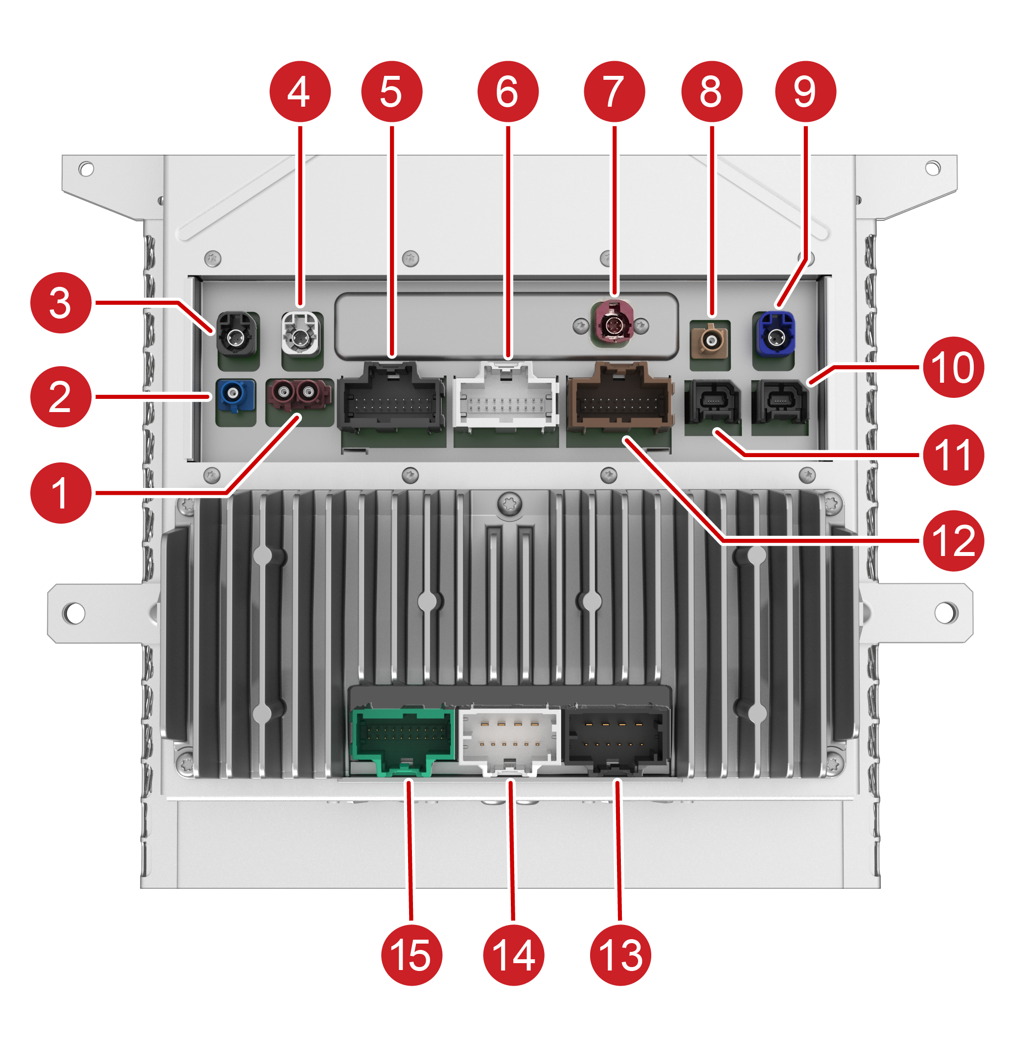
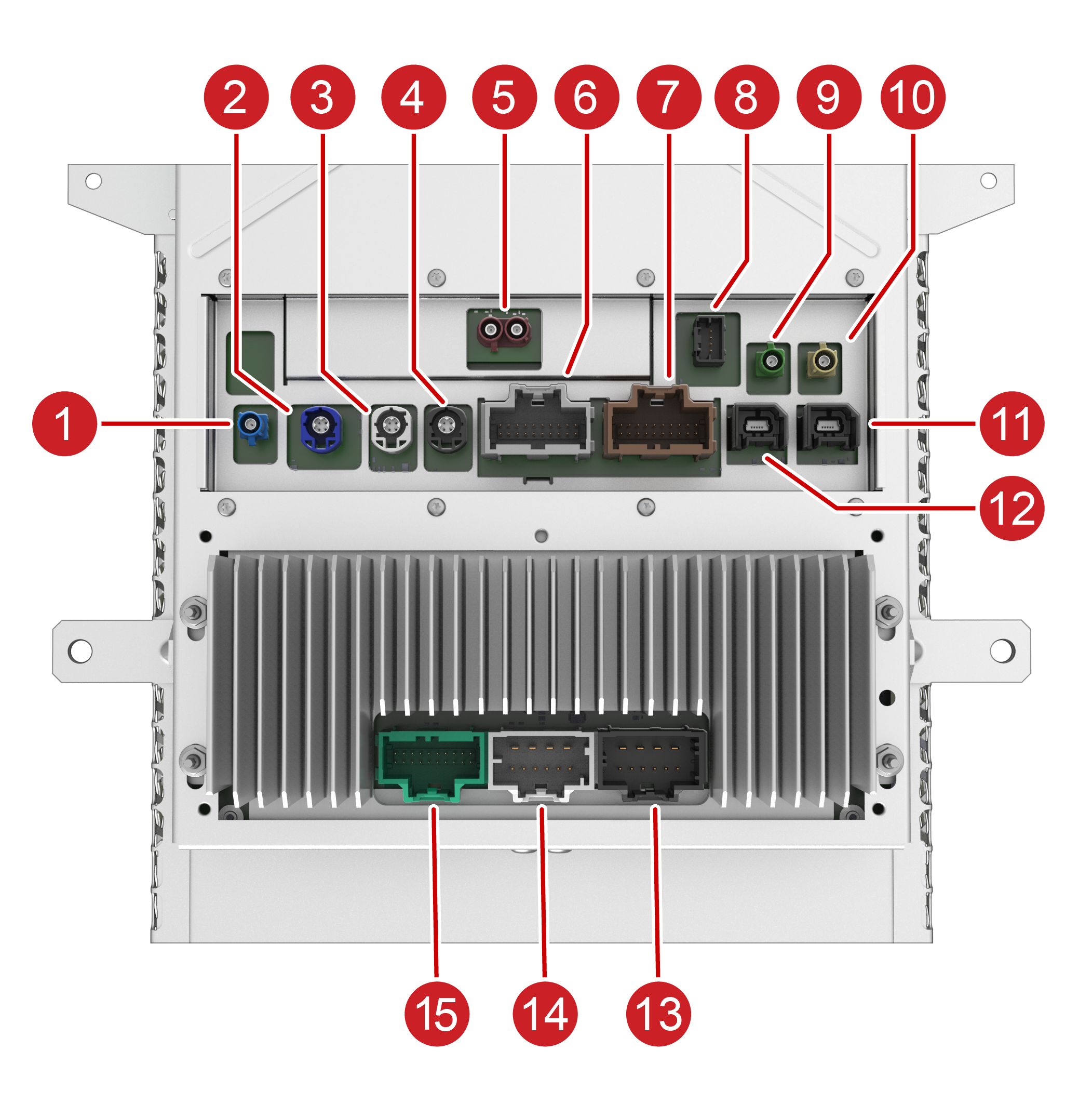
| Tegra MCU | Intel MCU |
| 1. GSM antenna 2. GPS antenna 3. Instrument Cluster 4. Diagnostic Port 5. LIN, Diagnostics 6. CAN, IO's 7. SIM Extender 8. WiFi antenna 9. Rear Camera 10. USB Port 11. USB Port 12. Analog 13. Main Power and Base Audio 14. Base Audio 15. Premium Audio |
1. GPS antenna - connector only present on MCU for PreAP/AP1 (part number 1451809-UX-X) 2. Rear Camera 3. Autopilot Ethernet 4. Instrument Cluster 5. GSM antenna 6. CAN, LIN, IO's 7. Analog 8. Radio Tuner 9. Bluetooth 10. WiFi antenna 11. USB Port 12. USB Port 13. Main Power and Base Audio 14. Base Audio 15. Premium Audio + Pedestrian Warning |
Right sidelink
 |
 |
|---|---|
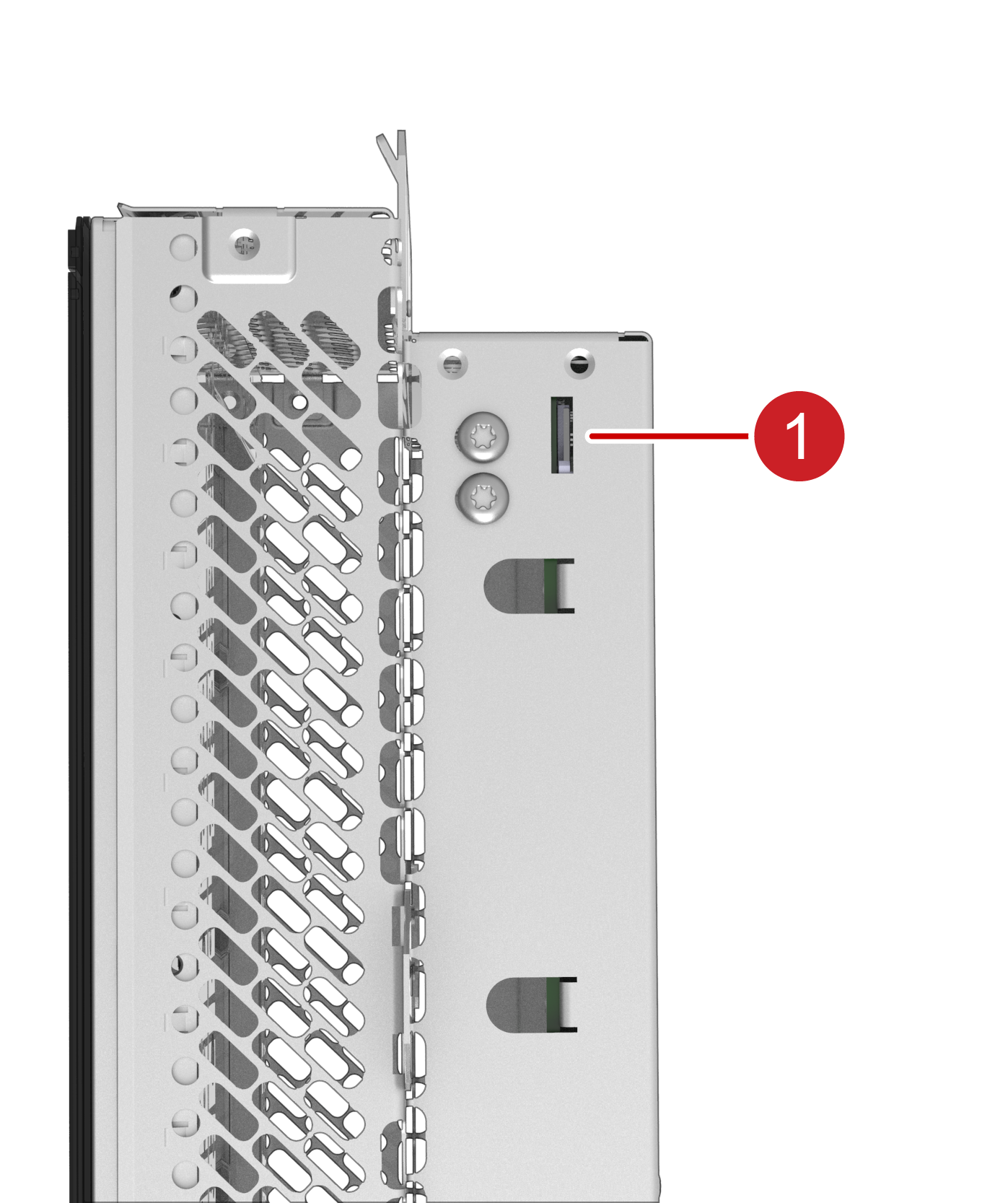
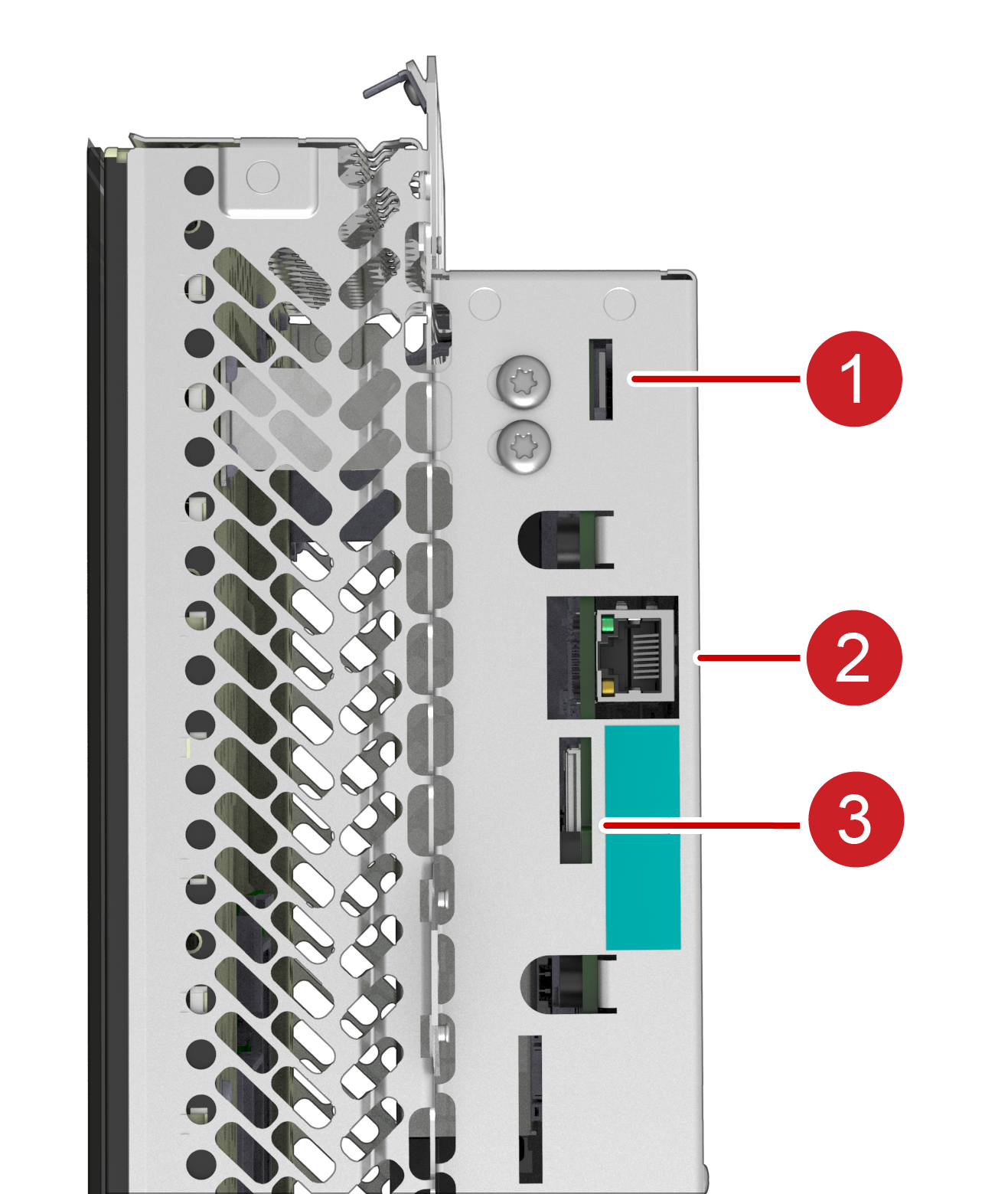
| Tegra MCU | Intel MCU |
| 1. Navigation Micro SD Card Slot | 1. Gateway SD Card Slot 2. Diagnostics Ethernet 3. SIM Card Slot |